Method for pressurizing the inner flow space of a flexible pipe intended for transporting hydrocarbons

a flexible pipe and flow space technology, applied in the direction of fluid-loss/gain rate measurement, fluid-tightness measurement, instruments, etc., can solve the problems of large deformation of the polymer sheath in the butt gap, appearance of cavitation and/or crazing on the polymer sheath, and insufficient cavitation to accommodate the deformation. , to achieve the effect of reducing, or even preventing, cavitation and crazing

Active Publication Date: 2021-01-12
TECH FRANCE SA
View PDF9 Cites 0 Cited by
  • Summary
  • Abstract
  • Description
  • Claims
  • Application Information

AI Technical Summary

Benefits of technology

[0018]The development of a method for pressurizing the inner flow space of a pipe making it possible to reduce, or even prevent, cavitation and crazing is therefore desired.

Problems solved by technology

At the internal pressure of the factory acceptance test, the deformation of the polymer sheath in the butt gap is considerable.
Under these conditions, these deformations may cause the appearance of cavitation and / or crazing on the polymer sheath.
The crazing phenomenon appears when the deformation is such that the cavitation alone no longer suffices to accommodate the deformation.
Over time, this cavitation and / or crazing may lead to the appearance of cracks and a loss of sealing of the polymer sheath.

Method used


Image

  • Method for pressurizing the inner flow space of a flexible pipe intended for transporting hydrocarbons
  • Method for pressurizing the inner flow space of a flexible pipe intended for transporting hydrocarbons
  • Method for pressurizing the inner flow space of a flexible pipe intended for transporting hydrocarbons

Examples


Embodiment Construction

[0171]Pressurization tests with two pressure maintenance sequences (n=1) were done with three different fluids, the natures, densities and viscosities of which are provided in table 1.

[0172]

TABLE 1density and kinematic viscosity of the three tested fluidsmeasuringMarcol 52Durasyn 174Imethodwateroiloilkinematic viscosityASTM D 4450.667.50412at 40° C.(mm2 / s)kinematic viscosityASTM D 4450.292.2050at 100° C.(mm2 / s)density at 20° C.ASTM D 40521825 to 834846

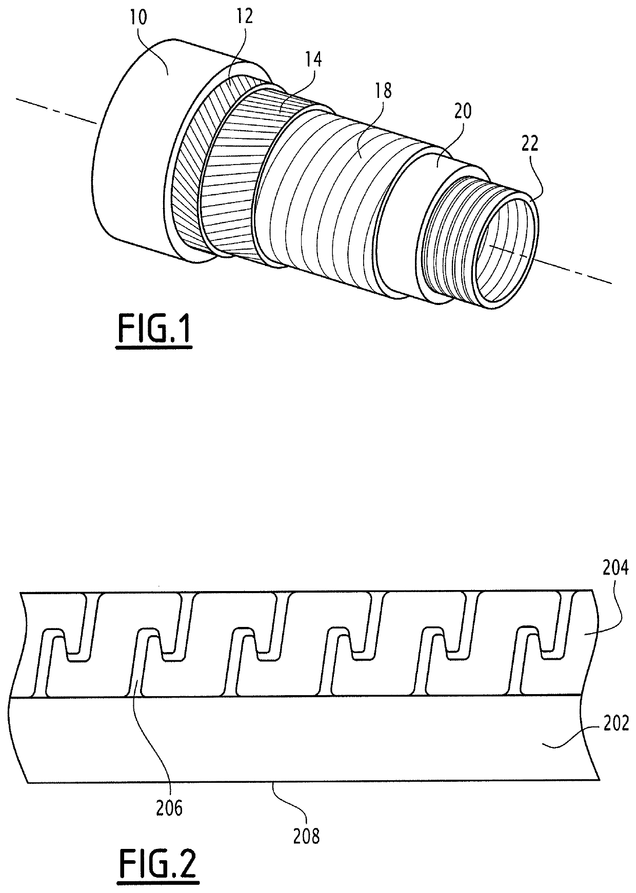
[0173]The three identical ST 63.60103 (Technip) flexible pipes used:

[0174]comprised, from the outside toward the inside of the pipe:[0175]an outer sealing polymer sheath (10),[0176]one or more tensile armor ply(plies) (12, 14),[0177]a pressure vault (18),[0178]an inner sealing polymer sheath (20) made from weakly plasticized PVDF (Gammaflex® TP22) (inner diameter of 77.50 mm), and[0179]a metal carcass (22),[0180]had an initial length of the flexible pipe (with tips) of 5.67 m, an inner diameter of 2.5″, an outer diameter of 142 mm, a h...


PUM

PropertyMeasurementUnit
inner pressure Piaaaaaaaaaa
pressureaaaaaaaaaa
kinematic viscosityaaaaaaaaaa

Abstract

The present application relates to a method for pressurizing the inner flow space of an underwater flexible pipe intended for transporting hydrocarbons, comprising the following steps:a) providing a flexible pipe comprising a reinforcing layer made up of a short-pitch winding of at least one metal wire with noncontiguous turns around a thermoplastic polymer sheath defining an inner space, thenb) filling the inner space of the flexible pipe with an oil, thenc) increasing the inner pressure Pi of the flexible pipe to at least 10 MPa, the inner pressure being exerted by said oil, thend′) maintaining the inner pressure Pi of the flexible pipe at a pressure of at least 10 MPa for a time D of at least one minute,characterized in that said oil has a kinematic viscosity at 40° C., measured according to the ASTM D445 standard, of more than 10 mm2 / s. This method makes it possible to reduce, or even prevent, the appearance of cavitation and crazing on the polymer sheath.

Description

CROSS-REFERENCE TO RELATED APPLICATIONS[0001]The present application is a 35 U.S.C. §§ 371 national phase conversion of PCT / EP2016 / 075753, filed Oct. 26, 2016, which claims priority of French Patent Application No. 15 60255, filed Oct. 27, 2015, the contents of which are incorporated by reference herein. The PCT International Application was published in the French language.TECHNICAL FIELD[0002]The present invention relates to a method for pressurizing the inner flow space of a flexible pipe intended for transporting hydrocarbons in deep water.TECHNICAL BACKGROUND[0003]Flexible pipes may be used at a great depth, typically up to 3000 meters deep. They allow the transport of fluids, in particular hydrocarbons, having a temperature typically reaching 130° C. and even able to exceed 150° C., and an inner pressure that may reach 100 MPa (1000 bar), or even 150 MPa (1500 bar).[0004]Flexible pipes for transporting hydrocarbons generally include, from the outside toward the inside of the p...

Claims


Application Information

Patent Timeline
Patent Type & Authority Patents(United States)
IPC IPC(8): F16L11/08G01M3/28G01M3/04B29C48/09B29C53/58
CPCF16L11/083F16L11/081G01M3/04G01M3/2815B29C48/09B29C53/582F16L11/08G01M3/28G01N3/12
Inventor EPSZTEIN, THOMASBRUSSELLE-DUPEND, NADÈGELEFEBVRE, XAVIER
Owner TECH FRANCE SA
Why Eureka
Try Eureka