Controlling intake valves in an internal combustion engine

a technology of intake valve and internal combustion engine, which is applied in the direction of valve drives, machines/engines, non-mechanical valves, etc., can solve the problems that the type of airflow into the combustion chamber from the inlet ports cannot be optimized for high efficiency and low pollutant emissions, and achieve the effect of smooth transition from the second mode to the first mod

Active Publication Date: 2021-02-02
JAGUAR LAND ROVER LTD
View PDF10 Cites 2 Cited by
  • Summary
  • Abstract
  • Description
  • Claims
  • Application Information

AI Technical Summary

Benefits of technology

[0011]This provides the advantage that the way in which air circulates within the combustion chamber may be changed in a way that allows efficient and stable combustion of fuel over a wide range of engine loads.
[0066]This provides the advantage that different types of air circulation may be provided in the combustion chamber depending upon engine load requirements.

Problems solved by technology

A problem with such existing systems is that the type of airflow into the combustion chamber from the inlet ports cannot be optimized for high efficiency and low pollutant emissions for the full range of magnitudes of torque that may be required from the engine.

Method used


Image

  • Controlling intake valves in an internal combustion engine
  • Controlling intake valves in an internal combustion engine
  • Controlling intake valves in an internal combustion engine

Examples


Embodiment Construction

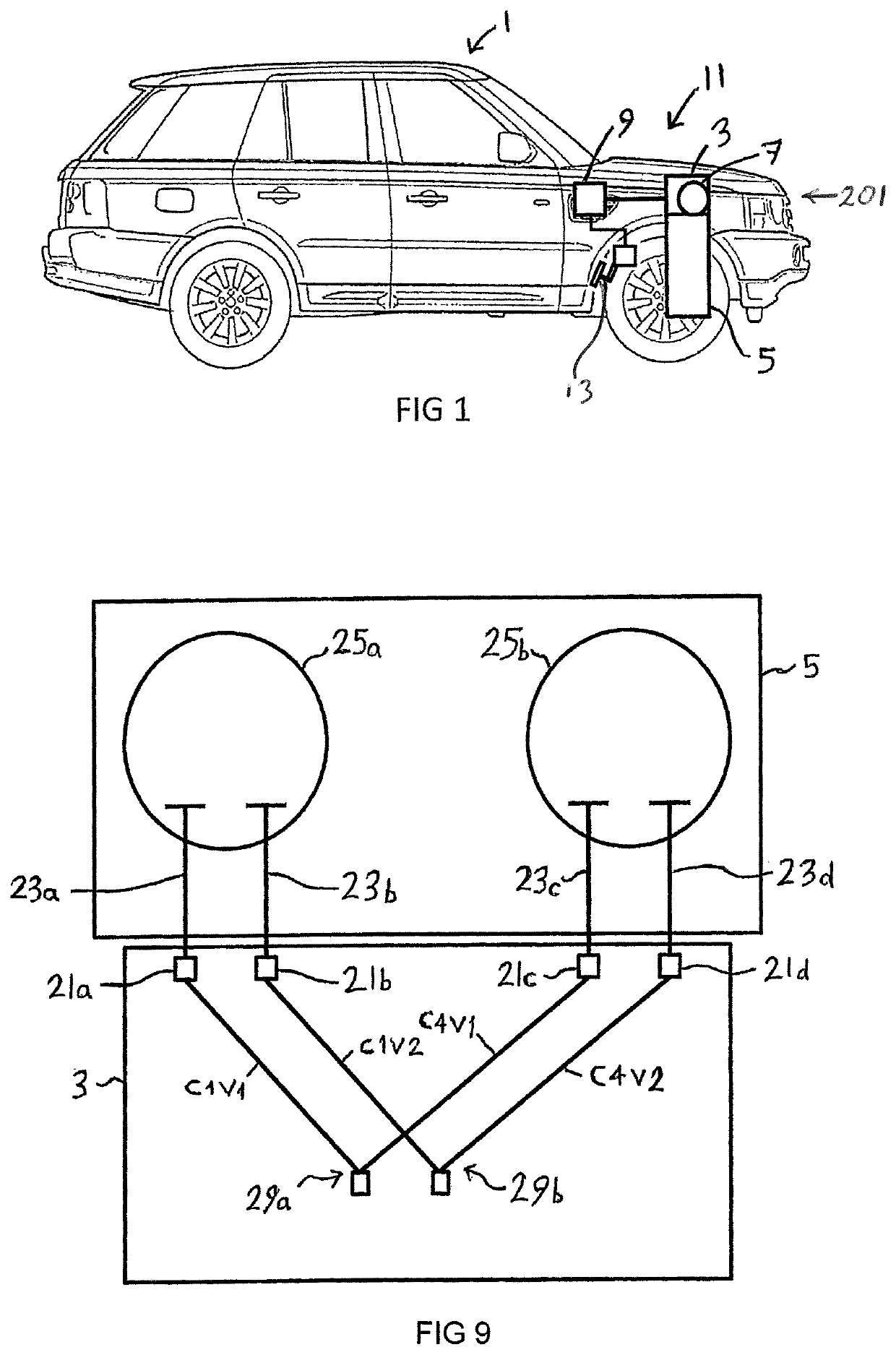
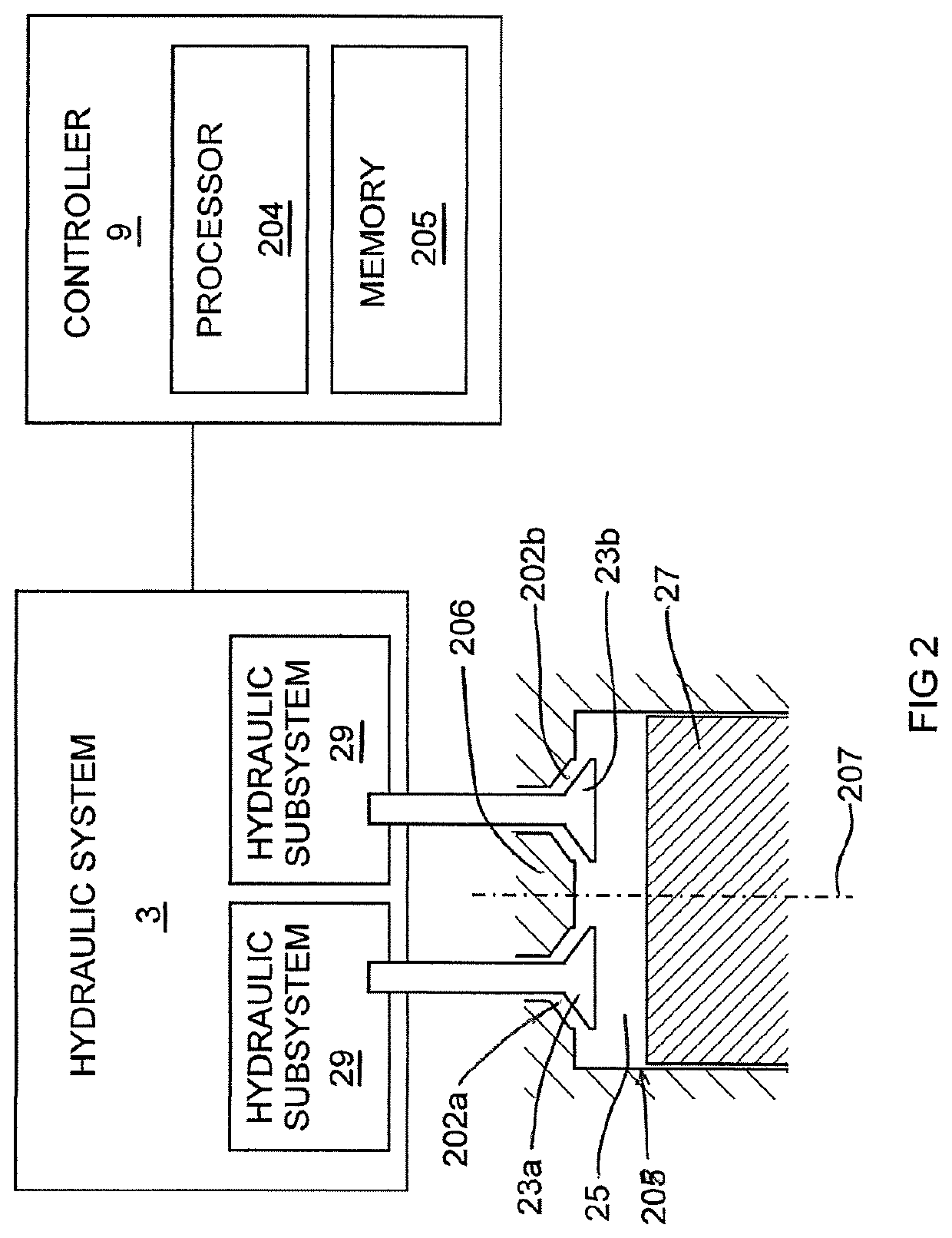
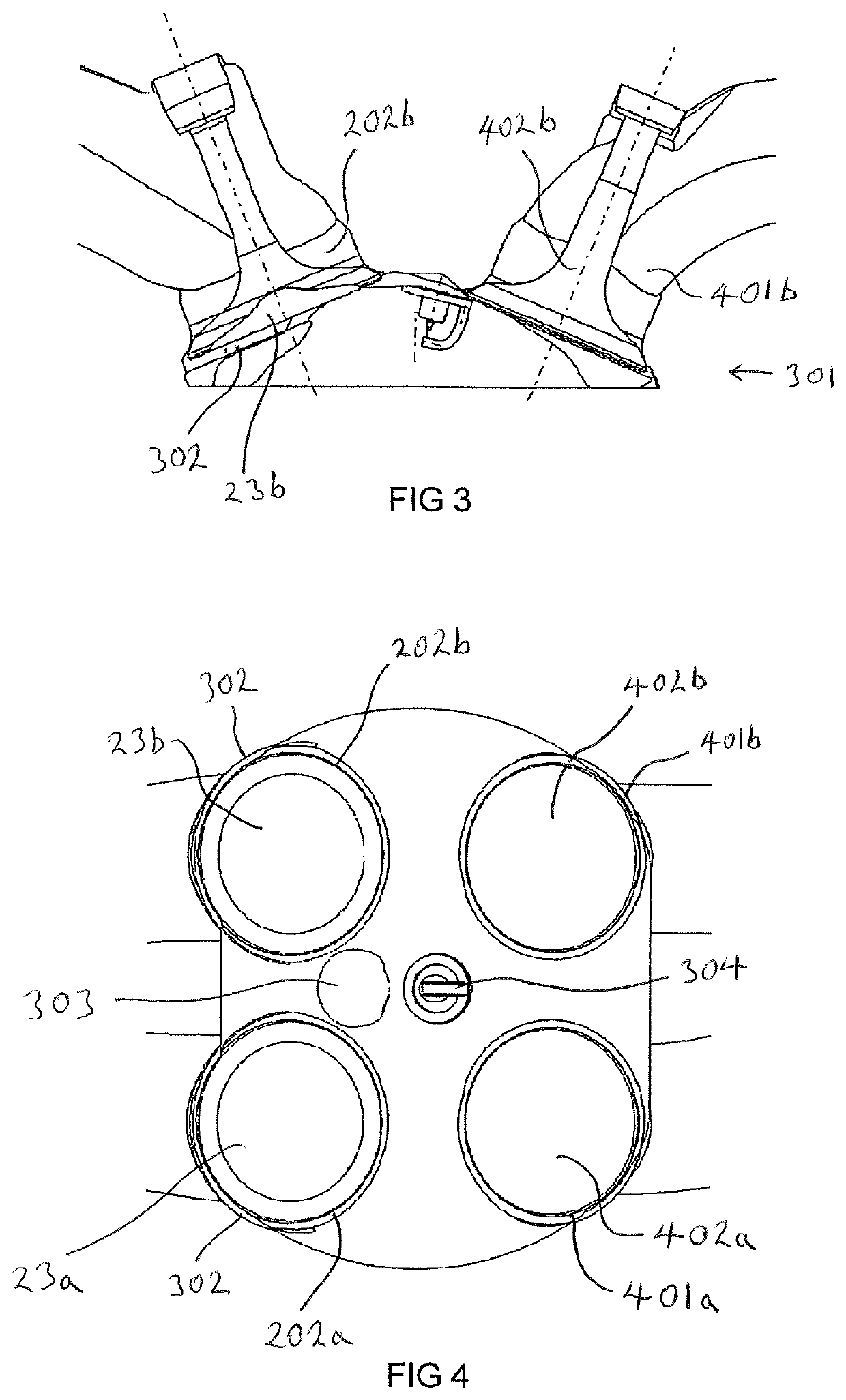
[0099]The Figures illustrate an apparatus 201 for controlling intake valves 23 in an internal combustion engine 5, the apparatus comprising: a hydraulic system 3 configured to hydraulically actuate a first intake valve 23a and a second intake valve 23b of a first combustion chamber 25 of an internal combustion engine 5; and a controller 9 configured to control the hydraulic system 3 in at least a first mode of operation and a second mode of operation, wherein in the first mode of operation, the controller 9 is configured to control the hydraulic system 3 to cause lifting of the first and second intake valves 23a, 23b of the first combustion chamber 25 during each intake stroke of a respective cylinder piston 27, and in a second mode of operation, the controller 9 is configured to control the hydraulic system 3 to cause lifting of the first intake valve 23a of the first combustion chamber 25 during an intake stroke of the respective cylinder piston 27 and disable actuation of the sec...


PUM


Abstract

An apparatus (201) and method for controlling intake valves (23) in an internal combustion engine (5), as well as an internal combustion engine and a vehicle comprising the apparatus, and an electronic processor for performing the method is disclosed. The apparatus comprises a hydraulic system (3) configured to hydraulically actuate a first intake valve (23a) and a second intake valve (23b) of a first combustion chamber (25) of an internal combustion engine (5). The apparatus also includes a controller (9) configured to control the hydraulic system (3) in at least a first mode of operation and a second mode of operation. In the first mode of operation, the controller (9) is configured to control the hydraulic system (3) to cause lifting of the first and second intake valves (23a, 23b) of the first combustion chamber (25) during each intake stroke of a respective cylinder piston (27). In the second mode of operation, the controller (9) is configured to control the hydraulic system (3) to cause lifting of the first intake valve (23a) of the first combustion chamber (25) during an intake stroke of the respective cylinder piston (27) and disable actuation of the second intake valve (23b) of the first combustion chamber (25) during that intake stroke.

Description

TECHNICAL FIELD[0001]The present disclosure relates to an apparatus and method for controlling intake valves in an internal combustion engine, as well as an internal combustion engine and a vehicle comprising the apparatus, and an electronic processor for performing the method. In particular, but not exclusively it relates to an apparatus and method for controlling intake valves in an internal combustion engine in a road vehicle.[0002]Aspects of the invention relate to an apparatus, an internal combustion engine, a vehicle, a method and a control means comprising an electronic controller.BACKGROUND[0003]At a predetermined time during a combustion cycle of an internal combustion engine, an intake valve (or inlet poppet valve) is lifted away from a valve seat and into a combustion chamber, to open an inlet port and allow the intake of air into the combustion chamber through the inlet port. At a later predetermined time during the combustion cycle, the intake valve is returned to the v...

Claims


Application Information

Patent Timeline
Patent Type & Authority Patents(United States)
IPC IPC(8): F02D13/02F01L9/02F02B31/04F02B31/00F01L9/10F01L9/14
CPCF02D13/0257F01L9/025F02B31/04F02B2031/006F01L1/053F01L1/08F01L1/26F01L1/267F01L3/06F01L13/0005F01L2800/06Y02T10/12F01L9/14F01L9/10
Inventor MCALLISTER, MATTHEW
Owner JAGUAR LAND ROVER LTD
Why Eureka
Try Eureka