Heat conductive oil furnace using emulsifying coke mortar vortex burning device

A heat-conducting oil furnace and cyclone combustion technology, which is applied in the direction of using multiple fuels for combustion, the combination of multiple burners, and the supply of air/fuel for combustion, can solve the problem of failing to reach the melting point of emulsified coke slurry ash and slag, and the inability to Problems such as liquefaction of emulsified coke slurry ash and complex structure of combustion chamber

Inactive Publication Date: 2007-08-22
广州迪森热能设备有限公司
View PDF4 Cites 1 Cited by
  • Summary
  • Abstract
  • Description
  • Claims
  • Application Information

AI Technical Summary

Problems solved by technology

It can be seen from the above analysis that, firstly, the backfired coal-water slurry liquid slagging combustion furnace is not suitable for the combustion of emulsified coke slurry; secondly, the combustion chamber temperature of the backfired coal water slurry liquid slagging combustion furnace is still low The ash melting point of the emulsified coke slurry ash cannot be reached, and the emulsified coke slurry ash cannot be liquefied; finally, the combustion chamber structure of the reverse combustion type coal-water slurry liquid slagging combustion furnace is complicated, and the manufacturing cost is high
[0007] Finally, in order to make the system operate continuously and normally, the slag receiving device at the lower part of the burner must be replaced in time, and the liquid slag also contains a large amount of waste heat that can be used. If the liquid slag is directly flowed into the slag receiving device, it will cause waste of energy

Method used


Image

  • Heat conductive oil furnace using emulsifying coke mortar vortex burning device
  • Heat conductive oil furnace using emulsifying coke mortar vortex burning device
  • Heat conductive oil furnace using emulsifying coke mortar vortex burning device

Examples


Embodiment 1

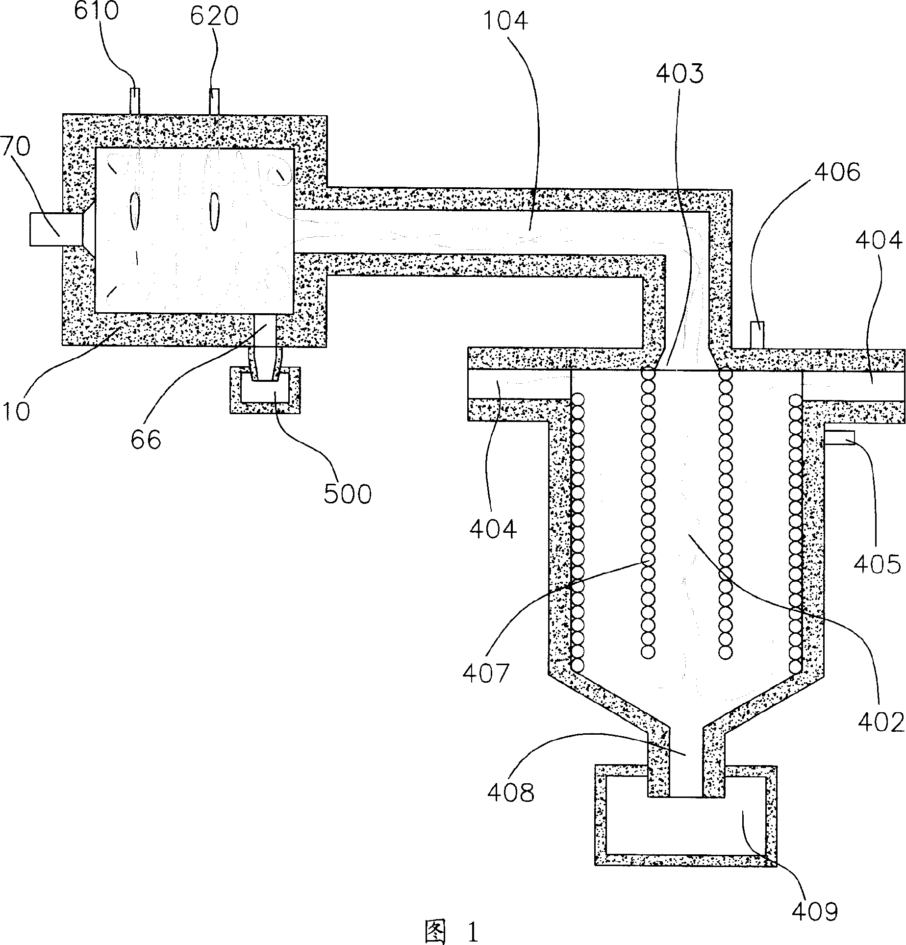
[0054] Please refer to Fig. 1, the heat transfer oil furnace using the emulsified coke slurry cyclone combustion device of the present invention includes a vertical oil furnace body and an emulsified coke slurry cyclone combustion device. Wherein, the oil furnace body includes a furnace chamber 402, a flame inlet 403 provided on the top wall of the furnace chamber 402, two flue gas outlets 404 provided on the side wall of the furnace chamber 402, an oil inlet 405 and an oil outlet arranged outside the furnace chamber 402. The oil port 406, a heat conduction oil pipe 407 coiled and arranged in the furnace chamber 402 with both ends communicating with the oil inlet 405 and the oil outlet 406 respectively, the secondary slag outlet 408 set in the lower part of the furnace chamber 402 and the secondary slag outlet 408 arranged in the secondary slag The secondary slagging device 409 below the outlet 408. The emulsified coke slurry cyclone combustion device includes a shell 10 , an ...

Embodiment 2

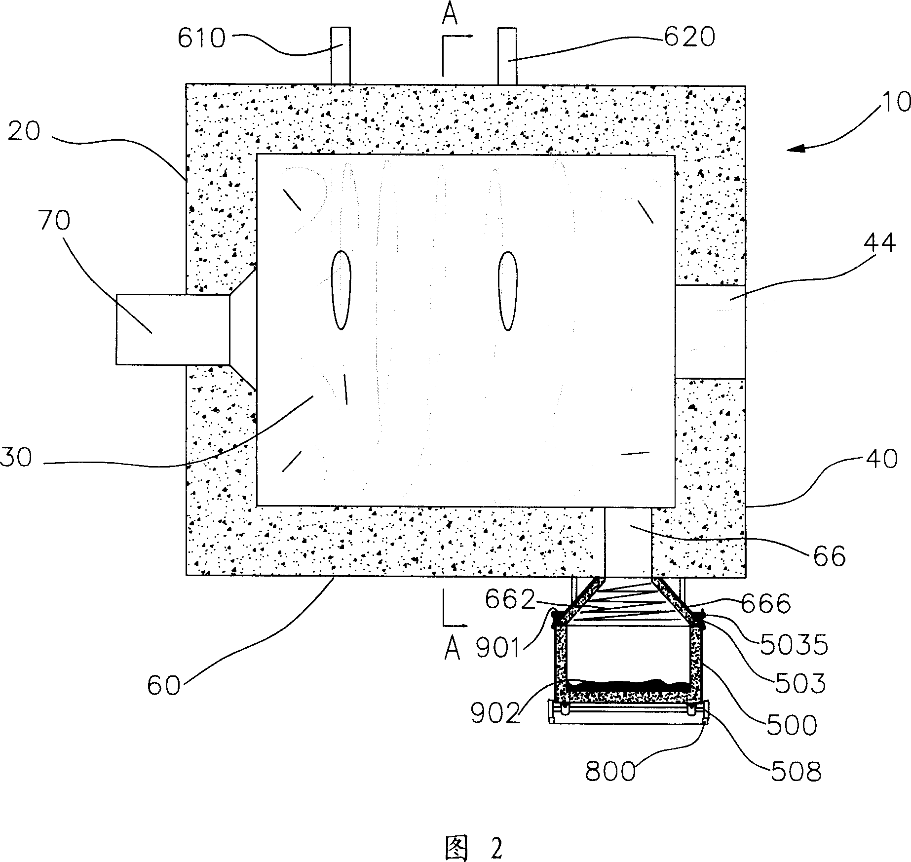
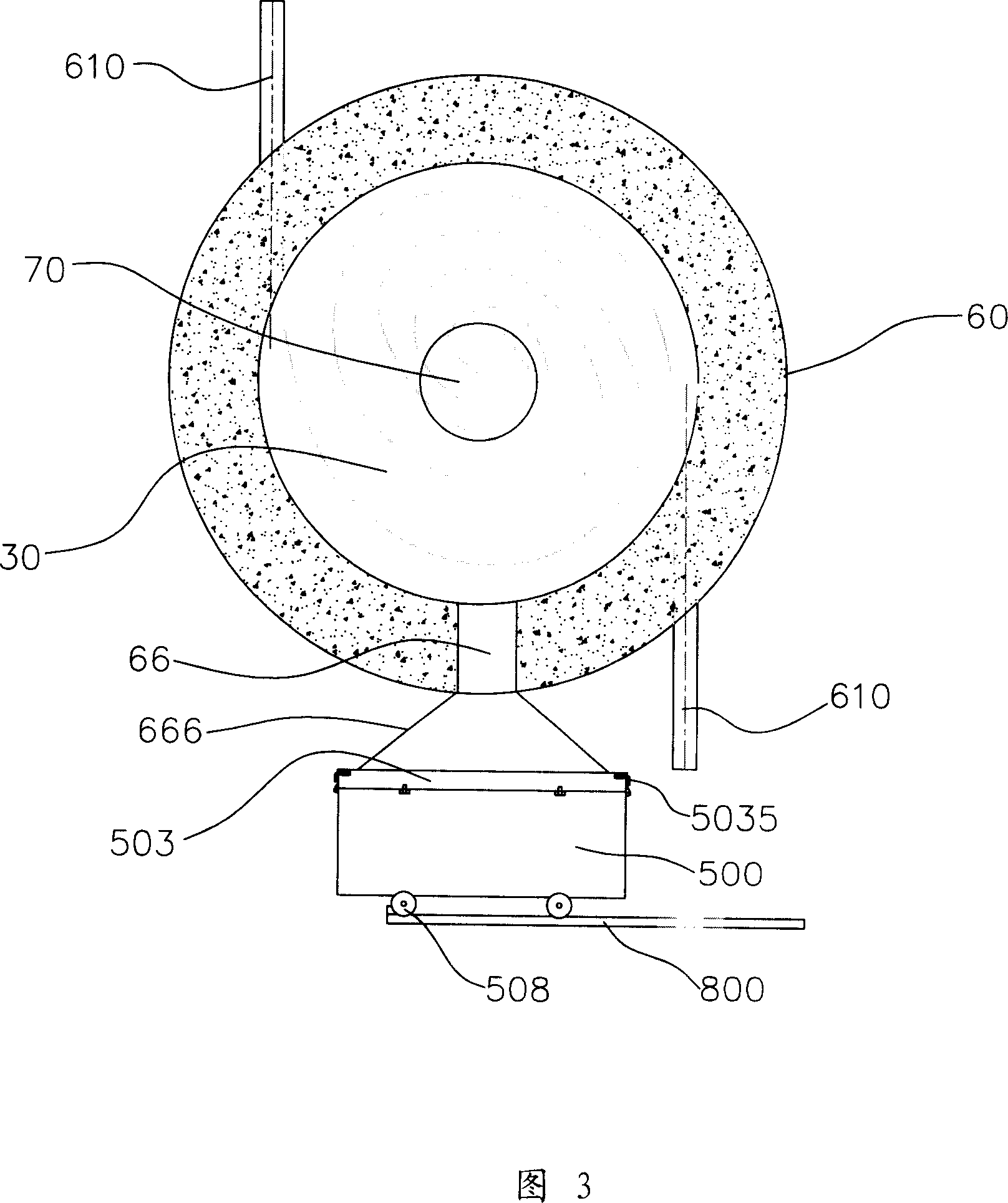
[0076] Please refer to Figure 4 and Figure 5, this embodiment is similar to Embodiment 1, the difference is:

[0077] Five heat-conducting oil pipes 407 are coiled and arranged in the furnace cavity 402 , and each heat-conducting oil pipe 407 corresponds to an oil inlet 405 and an oil outlet 406 respectively.

[0078] Since the amount of slag discharged from the secondary slag outlet 406 is small, instead of alternately working slag discharge vehicles, a slag discharge container is used, and the slag discharge container is emptied or replaced at regular intervals.

[0079] The opening area of ​​the liquid slag outlet 66 on the inner wall of the side wall 60 is approximately equal to one-twentieth of the cross-sectional area of ​​the combustion space 30 .

[0080] The vertical distance between the inner wall of the front end wall 20 and the inner wall of the rear end wall 40 is 1.5 times the inner diameter of the combustion space 30 .

[0081] The diameter of the outlet 44 is ...

Embodiment 3

[0090] This embodiment is similar to Embodiment 1, the difference is:

[0091] The heat-conducting oil pipes 407 are distributed into two rows in the furnace cavity, and each row includes about ten cross-sections of the heat-conducting oil pipes from top to bottom.

[0092] The heat-conducting oil furnace using the emulsified coke slurry cyclone combustion device is provided with two liquid slag outlets 66 of the same size distributed at intervals, and the opening area of ​​each liquid slag outlet 66 on the inner wall of the side wall 60 is approximately equal to the cross-sectional area of ​​the combustion space one-thirtieth of.

[0093] The two liquid slag outlets 66 are surrounded by the same transition cavity 666 and are connected to the slag holding space 505 of the same slag discharge vehicle 500 .

[0094] The vertical distance between the inner wall of the rear end wall 40 and the inner wall of the front end wall 20 is 4 times the inner diameter of the combustion spa...


PUM


Abstract

The invention discloses a heat-conducting oil stove used the emulsifying burnt plasma vortex burning device. It includes the oil stove body and the emulsifying burnt plasma vortex burner which includes the shell composed by the front wall, the back wall and the side wall. The burning room is formed in the shell. At least one emulsifying burnt plasma vortex burner and at least one oil burner or at least one gas burner is set in the front wall; an outlet is set in the back wall which is connected with the flame inlet of furnace chamber by the warm-air pipe. The two or above groups of tangential wind inlets are set on the shell side wall alternately; the outlet of the liquid slag is on the side wall of the burning room bottom which is near to the back wall. The invention uses the emulsifying burnt plasma as the fuel, so it can save the cost.

Description

technical field [0001] The invention relates to a heat-conducting oil furnace, more specifically, the invention relates to a heat-conducting oil furnace using an emulsified coke slurry combustion device. Background technique [0002] The natural energy that can be used by human beings is decreasing, but the human demand for energy is increasing. Therefore, all countries in the world are adjusting their energy structure to save the existing energy to the greatest extent. At the same time, environmental pollution has also become the focus of attention of people all over the world in recent years. At present, the relatively clean energy used in heat transfer oil furnaces is mainly oil, natural gas or coal gas, etc. However, this has greatly increased the fuel cost of heat transfer oil furnaces, seriously affecting the survival of enterprises that use and manufacture heat transfer oil furnaces. [0003] For this reason, those skilled in the art are working hard to develop new ...

Claims


Application Information

Patent Timeline
Patent Type & Authority Applications(China)
IPC IPC(8): F24H1/40F23C1/00F23C5/00F23D23/00F23D17/00F23J1/08F23L1/00
Inventor 常厚春李祖芹马革刘效洲
Owner 广州迪森热能设备有限公司
Why Eureka
Try Eureka