
A Swirling Vortex Combustion Chamber

A technology of combustion chamber and vortex, which is applied in the direction of combustion chamber, continuous combustion chamber, combustion method, etc., can solve the problems of difficult oil and gas matching, difficult adjustment of outlet temperature distribution, etc., to achieve widening point flameout boundary, compact head, and reduce emissions Effect

Active Publication Date: 2022-04-08
NANJING UNIV OF AERONAUTICS & ASTRONAUTICS
View PDF7 Cites 1 Cited by
  • Summary
  • Abstract
  • Description
  • Claims
  • Application Information

AI Technical Summary

Problems solved by technology

Therefore, compared with the conventional combustor, the oil and gas matching of the trapped vortex combustor is more difficult, and the outlet temperature distribution is more difficult to adjust

Method used


Image

  • A Swirling Vortex Combustion Chamber
  • A Swirling Vortex Combustion Chamber
  • A Swirling Vortex Combustion Chamber

Examples


Embodiment Construction

[0045] Below in conjunction with accompanying drawing, technical scheme of the present invention is described in further detail:

[0046] This invention may be embodied in many different forms and should not be construed as limited to the embodiments set forth herein. Rather, these embodiments are provided so that this disclosure will be thorough and complete, and will fully convey the scope of the invention to those skilled in the art. In the drawings, components are exaggerated for clarity.

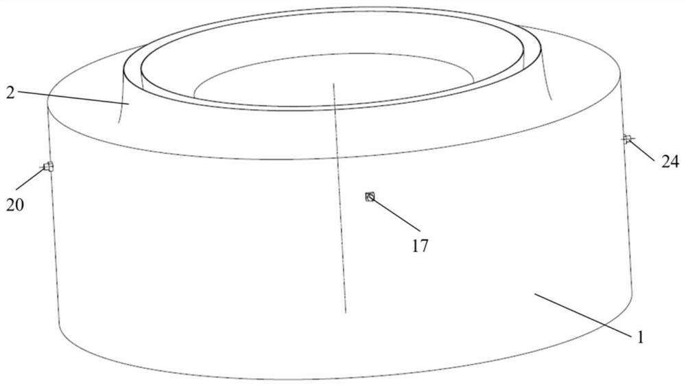
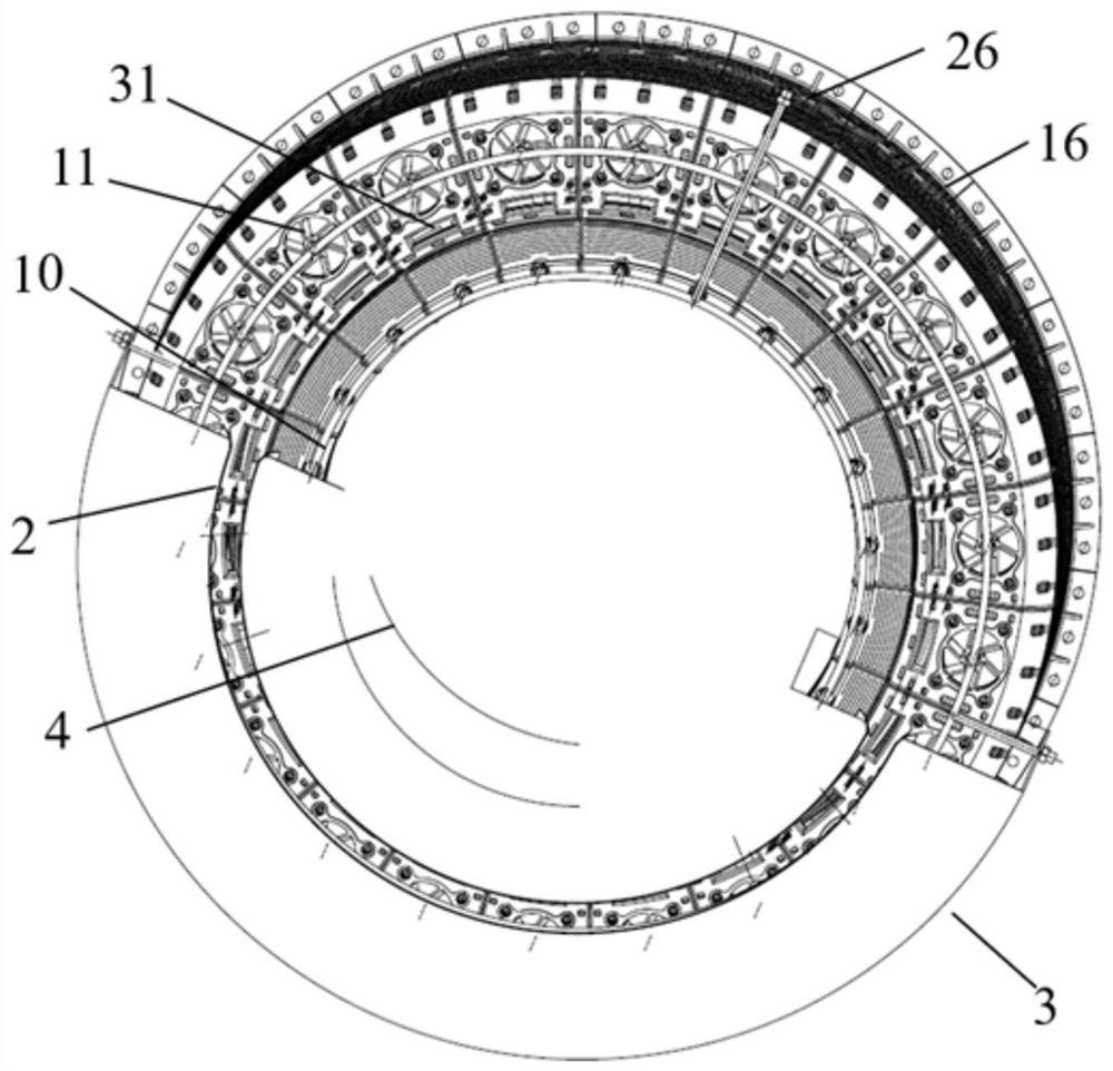
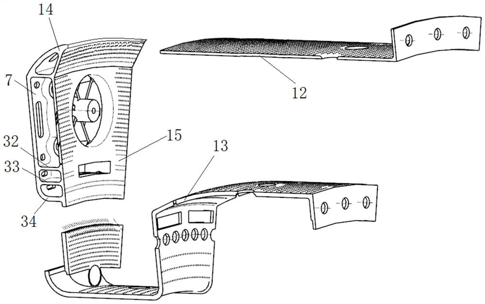
[0047] Please refer to Figure 1 to Figure 5 As shown, the present invention discloses a swirling stationary vortex partition combustion chamber, including a diffuser, an inner casing, an outer casing, an oil supply module, a high-energy ignition nozzle and a flame tube;

[0048] like figure 1 As shown, the diffuser is arranged at the entrance of the combustion chamber, and is used to decelerate and pressurize the gas to enter the combustion chamber;

[0049] like image 3 , Figu...


PUM


Abstract

The invention discloses a swirling vortex zone combustion chamber, which comprises a diffuser, an inner casing, an outer casing, an oil supply module, a high-energy ignition nozzle and a flame tube. The diffuser passes all the required airflow through the combustion chamber, decelerating and boosting the incoming airflow. The inner and outer casings and the wall of the flame tube divide the combustion chamber into inner and outer ducts and the inner area of ​​the flame tube. The flame tube is composed of the duty-level trapped vortex area and the main combustion level swirl area: the trapped vortex area is a single concave cavity structure formed by the geometry of the flame tube; the main combustion level is composed of a single-stage axial swirler and a channel-support plate structure constitute. The oil supply system is divided into three routes, duty-level fuel supply, main fuel-level channel fuel supply, and main fuel-level cyclone fuel supply. The high-energy ignition nozzle extends into the single-cavity structure. The invention realizes combustion with a high oil-gas ratio and widens the stable working range of the high-temperature-rising combustion chamber through the staged combustion zone setting.

Description

technical field [0001] The invention relates to the technical field of new-concept gas turbine combustion, in particular to a swirling stationary vortex partition combustion chamber, which is mainly used as a main combustion chamber of an aero-engine, and can also be used as a combustion chamber for ground and marine gas turbines. Background technique [0002] With the further development of aero-engine technology, the thrust-to-weight ratio continues to increase, the inlet temperature of the combustion chamber increases, the oil-gas ratio and temperature rise of the combustion chamber increase, and the requirements for the performance of the combustion chamber gradually increase, but at the same time, the weight of the combustion chamber is limited. Further increase, therefore, the development of the high-fuel ratio combustion chamber is facing many technical challenges: 1. Stable operation in a wider range, mainly to solve the combustion stability under low power state and ...

Claims


Application Information

Patent Timeline
Patent Type & Authority Patents(China)
IPC IPC(8): F23R3/58F23R3/38F23R3/48
CPCF23R3/58F23R3/38F23R3/48
Inventor 何小民郭煜玺张秋峰张净玉
Owner NANJING UNIV OF AERONAUTICS & ASTRONAUTICS
Learn More