
Spiral yarn structure, manufacturing method and manufacturing device thereof and textile utilizing the same

a manufacturing method and spiral yarn technology, applied in the direction of yarn, textiles and paper, etc., can solve the problems of difficult control of the torque of the spiral yarn, post processing problems of the textile, shrinkage problems, etc., and achieve the reduction of the torque, shrinkage, torque and skew of the spiral yarn. , the effect of small twis

Active Publication Date: 2021-02-09
CORETEK FIBERS LTD
View PDF11 Cites 0 Cited by
  • Summary
  • Abstract
  • Description
  • Claims
  • Application Information

AI Technical Summary

Benefits of technology

The spiral yarn structure significantly reduces shrinkage, torque, and skew in textiles while maintaining strength, thereby enhancing fabric quality and reducing labor-intensive pre-shrinking processes, and minimizing fabric loss during manufacturing.

Problems solved by technology

Due to mechanical limitations of loom / knit machines or torque generated in twisted yarns used for fabric, thin and light-weighted textile made of the yarns formed by cotton, cellulose or other non-thermoset material may have a shrinkage up to 8%-15%, their torque is difficult to be controlled under 3% and their skew may also be 25-30%.
This causes post processing problems for the textile and shrinkage problem for cloth made of the textile.
The elastomeric yarns may increase total weight of the cloth and possibly cause uneven quality of the cloth.
Since the tensionused in cloth winding may even cause unstable occurrence of shrinkage and torque, the cloth must be loosen and pre-shrunk (washed by water) before the cloth is cut, thereby avoiding the shrinkage and torque problem.
Such post-processes for cloth products cause more labors and troubles.

Method used

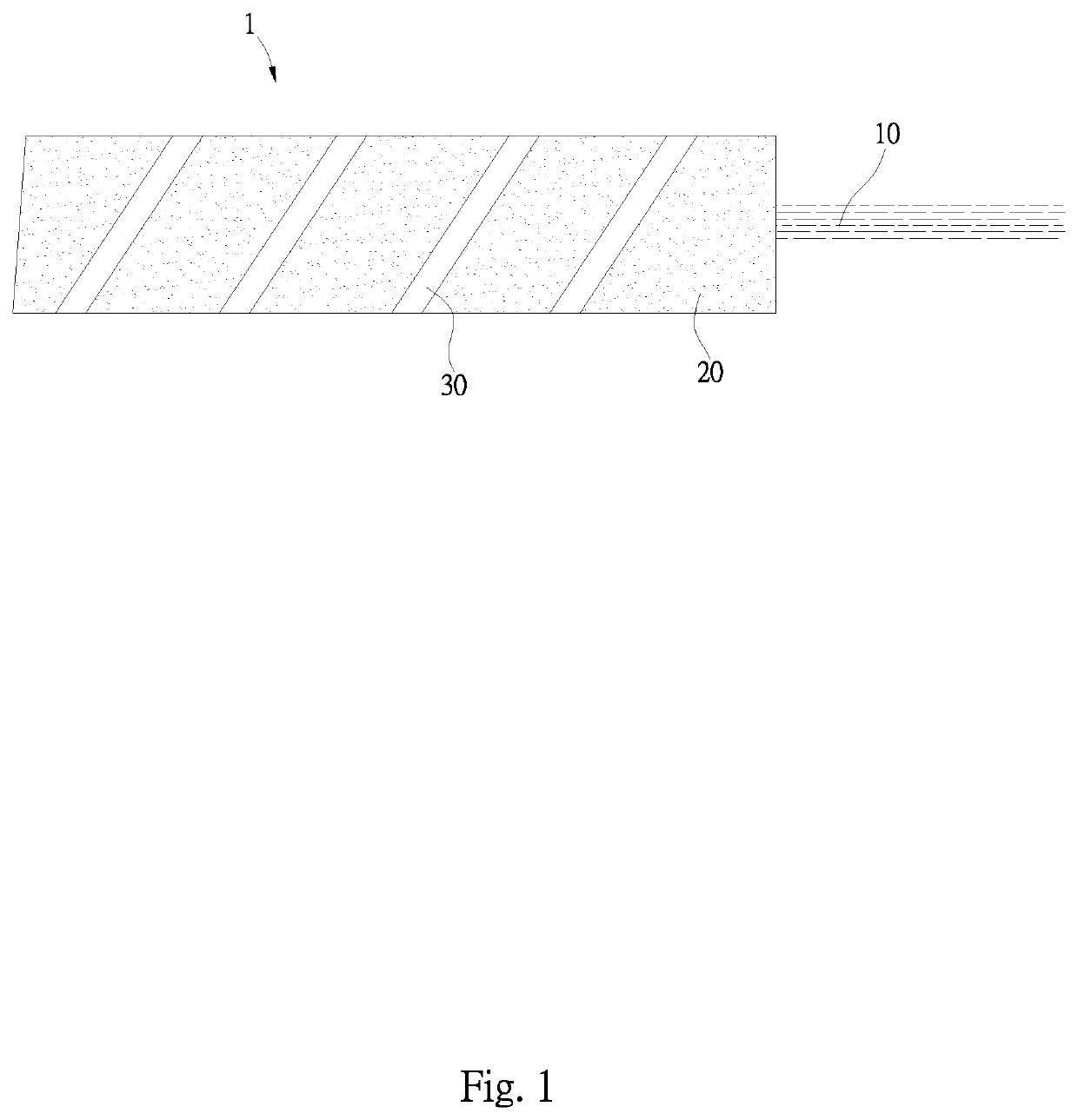
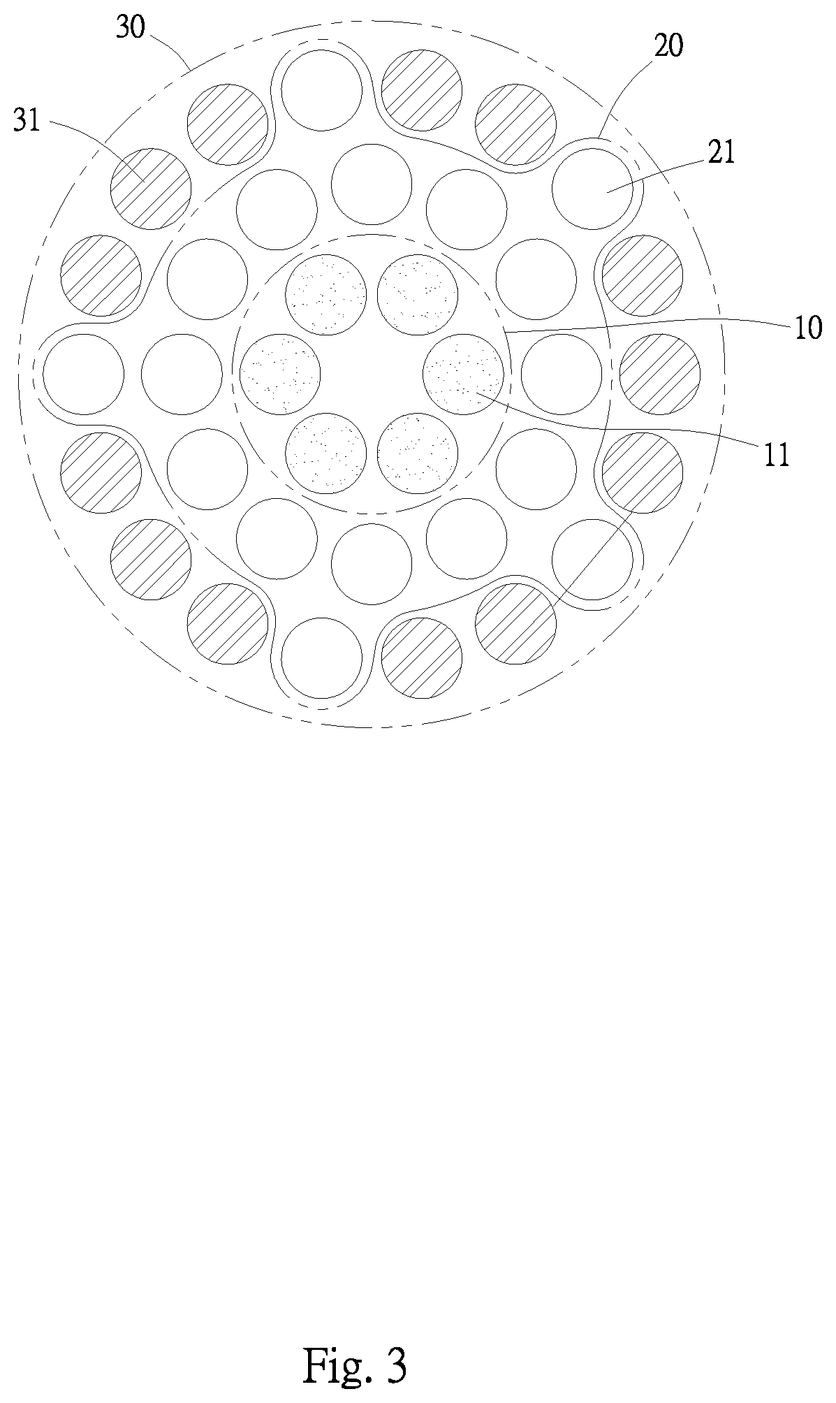

Image

  • Spiral yarn structure, manufacturing method and manufacturing device thereof and textile utilizing the same
  • Spiral yarn structure, manufacturing method and manufacturing device thereof and textile utilizing the same
  • Spiral yarn structure, manufacturing method and manufacturing device thereof and textile utilizing the same

Examples


Embodiment Construction

[0018]The following description is of the best-contemplated mode of carrying out the invention. This description is made for the purpose of illustrating the general principles of the invention and should not be taken in a limiting sense. The scope of the invention is best determined by reference to the appended claims.

[0019]Referring to FIGS. 1, 2 and 3, a spiral yarn 1 of the present includes a core yarn 10, a cover yarn 20 enclosing the core yarn 10 and a wrap yarn 30 wrapping the cover yarn 10 at a twist factor K≤3. The wrap yarn 30 wraps an outer side of the cover yarn 20 to form the spiral yarn 1 having a count ranging from 40 Ne to 80 Ne. The twist direction of the spiral yarn 1 is Z-twist or S-twist. In this embodiment, the twist direction of the spiral yarn 1 is Z-twist, but one of the core yarn and the wrap yarn has a twist direction of S-twist which is different from the twist direction of the spiral yarn 1.

[0020]The core yarn 10 includes at least one core filament 11 whic...


PUM

PropertyMeasurementUnit
shrinkageaaaaaaaaaa
shrinkageaaaaaaaaaa
distanceaaaaaaaaaa

Abstract

A spiral yarn structure includes a core yarn comprising at least one core filament which is a filament fiber of 5-25D, a cover yarn comprising a plurality of cover fibers formed by stretching roves having a count ranging from 0.5 Ne to 2.0 Ne, wherein the cover fibers encloses the core yarn, and a wrap yarn wrapping the cover yarn at a twist factor K≤3, wherein the wrap yarn comprises at least one wrap filament which is a filament fiber of 5-25D, and the at least one wrap filament wraps an outer side of the cover yarn at an inclined angle to form the spiral yarn structure having a count ranging from 40 Ne to 80 Ne.

Description

BACKGROUND OF THE INVENTIONField of the Invention[0001]The invention relates to a spiral yarn structure, a manufacturing method and a manufacturing device thereof and a textile using the spiral yarn structure, and more particularly to a spiral yarn structure including a core yarn enclosed by a cover yarn formed by staple fibers and a wrap yarn wrapping the cover yarn, wherein the spiral yarn of the invention has smaller twist and torque, and shrinkage, torque and skew of fabric formed by the spiral yarn are thus reduced.Description of the Related Art[0002]Accordingly, vertical stripes, horizontal stripes or checkered stripes formed by vertical stripes and horizontal stripes are formed to enhance aesthetic of the cloth. Due to mechanical limitations of loom / knit machines or torque generated in twisted yarns used for fabric, thin and light-weighted textile made of the yarns formed by cotton, cellulose or other non-thermoset material may have a shrinkage up to 8%-15%, their torque is d...

Claims


Application Information

Patent Timeline
Patent Type & Authority Patents(United States)
IPC IPC(8): D02G3/38D02G1/02D02G1/14D02G3/04D02G3/26
CPCD02G3/38D02G1/028D02G1/14D02G3/04D02G3/26D10B2201/02D10B2201/20D10B2211/02D10B2211/04D10B2331/02D10B2331/04
Inventor HUANG, WEN-CHILYU, TING-YI
Owner CORETEK FIBERS LTD
Learn More