Electric coil, apparatus having at least two subcoils and manufacturing method therefor

a technology of electric coils and subcoils, applied in the direction of superconducting magnets/coils, magnetic bodies, instruments, etc., can solve the problems of more unfavorable geometric progression, and achieve the effect of symmetrical magnetic field

Active Publication Date: 2018-06-26
SIEMENS HEALTHCARE GMBH
View PDF15 Cites 0 Cited by
  • Summary
  • Abstract
  • Description
  • Claims
  • Application Information

AI Technical Summary

Benefits of technology

[0013]In other words, the at least two subcoils are formed such that the orientation of the superordinate tape conductor surface with respect to the centerpoint of the respective subcoil differs within such a pair. This opposing orientation of this at least one pair of subcoils initially inevitably allows for a more unfavorable geometric progression in the winding of the subcoils. For in order to achieve the opposing orientation of the superordinate surfaces when manufacturing the subwindings, the at least two conductor branches must be twisted counter to one another in their end regions. In an arrangement of the subcoils for the final coil apparatus, however, the individual subcoils of this pair can then be oriented counter to one another such that this torsion is largely eliminated and the conductor branches of the tape conductor are twisted only slightly in the finished coil apparatus and during its operation. This can achieve an improved service life and / or improved electrical properties of the tape conductor during operation of the coil apparatus. Furthermore, such an arrangement can reduce the space required for the end regions of the doubly connected tape conductor.
[0040]The at least two subcoils can in a preferable embodiment be wound simultaneously. If there are more than two subcoils, these subcoils can advantageously be wound with one another in pairs simultaneously in each case. This can usefully be carried out such that for each pair of subcoils a constantly equal number of windings is produced. In this way, a particularly symmetrical magnetic field can advantageously be achieved with the superordinate coil apparatus.

Problems solved by technology

This opposing orientation of this at least one pair of subcoils initially inevitably allows for a more unfavorable geometric progression in the winding of the subcoils.

Method used


Image

  • Electric coil, apparatus having at least two subcoils and manufacturing method therefor
  • Electric coil, apparatus having at least two subcoils and manufacturing method therefor
  • Electric coil, apparatus having at least two subcoils and manufacturing method therefor

Examples


Embodiment Construction

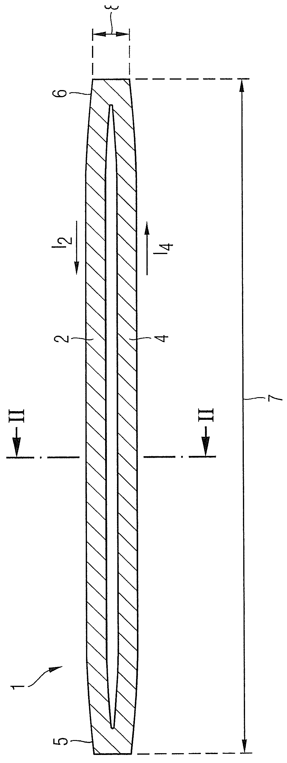
[0050]FIG. 1 shows the schematic top view of a superconducting tape conductor with a doubly connected topology, which is manufactured by slitting a singly connected superconducting tape conductor. In this example, the slitting is carried out by a laser.

[0051]A first exemplary embodiment of the invention is a magnetic coil for NMR spectroscopy. In this example, the length 7 of the originally singly connected tape conductor is 1000 m. This length may, however, also be substantially shorter or longer. In a magnetic coil for magnetic resonance imaging, the length may be a multiple of the length described here. The superconducting tape conductor comprises two approximately equally dimensioned conductor branches 2 and 4. A current I2 flows through the first conductor branch 2, and a current I4 flows in the opposite direction through the second conductor branch, so that a closed ring current flows through the entire doubly connected superconducting tape conductor 1. The width 8 of the orig...


PUM

PropertyMeasurementUnit
angleaaaaaaaaaa
angleaaaaaaaaaa
magnetic flux densitiesaaaaaaaaaa

Abstract

An electric coil apparatus has at least two subcoils from a superordinate doubly connected tape conductor. The coil apparatus has at least two conductor branches, each of the subcoils being wound from one of these conductor branches respectively. The conductor branches of the superordinate tape conductor have a superordinate first surface and a superordinate second surface facing away from this first surface. In a first subcoil, the first surface of the tape conductor faces a centerpoint of the first subcoil, and in a second subcoil, the second surface of the tape conductor faces a centerpoint of the second subcoil. Furthermore, in a manufacturing method of such a coil apparatus the two conductor branches are routed parallel to each other so as to dorm the subcoils.

Description

BACKGROUND OF THE INVENTION[0001]Field of the Invention[0002]The invention concerns an electric coil apparatus of the type having at least two subcoils made of a superordinate doubly-connected tape conductor, the tape conductor having at least two conductor branches and the subcoils each being wound from one of these conductor branches.[0003]Description of the Prior Art[0004]Superconducting coils are used to generate strong, homogeneous magnetic fields, with the superconducting coils being operated in sustained short-circuit current mode. Homogeneous magnetic fields with magnetic flux densities between 0.5 T and 20 T are needed, for example, for nuclear magnetic resonance spectroscopy (NMR spectroscopy) and for magnetic resonance imaging. These magnets are typically charged via an external current circuit and are then separated from the external power source as, in the resulting sustained short-circuit current mode, an almost loss-free current flow occurs via the superconducting coi...

Claims


Application Information

Patent Timeline
Patent Type & Authority Patents(United States)
IPC IPC(8): H01F1/00H01F41/12H01F41/04G01R33/34G01R33/381H01F6/06G01R33/3815
CPCH01F6/06G01R33/34023H01F41/048H01F41/12G01R33/381G01R33/3815
Inventor BATZ, OTTOBAYER, DIETMARFRANK, MICHAELVAN HASSELT, PETER
Owner SIEMENS HEALTHCARE GMBH
Why Eureka
Try Eureka