Remote control car with simple servo control system

A servo control system, a technology for remote control cars, applied in the field of remote control cars, can solve problems such as the gap between the motor speed and the expected speed, inaccurate control speed, vehicle body offset, jumping, etc., to achieve accurate speed regulation, saving quantity, and twisting small effect

Pending Publication Date: 2019-06-28
吴根飚
View PDF0 Cites 0 Cited by
  • Summary
  • Abstract
  • Description
  • Claims
  • Application Information

AI Technical Summary

Problems solved by technology

[0002] Existing low-end remote control cars such as toy remote control cars generally use cheap DC iron core brushed micro motors, such as FF130 motors, which have high speed and low torque, and need to drive the wheels through a reduction gear set to reduce the speed and increase the torque. At the same time, PWM is used to control the motor speed, but the PWM control speed is not accurate, so there is often a gap between the motor speed and the expected speed, especially there is often a large gap between the speeds of different motors, resulting in differences in wheel speed and vehicle body deviation. , jumping and other phenomena; for small remote control vehicles equipped with omnidirectional wheels such as Mecanum wheels, it is necessary to control the speed of each wheel more accurately to achieve stable omnidirectional movement. At this stage, conventional PWM speed regulation is difficult to meet the demand; Generally, it is necessary to use a servo motor to achieve more accurate control of the wheel speed, but the price of a servo motor is often higher than the cost of the entire toy remote control car. Therefore, due to cost considerations, none of the existing low-end remote control cars use servo motors. No other low-cost solution exists

Method used


Image

  • Remote control car with simple servo control system
  • Remote control car with simple servo control system
  • Remote control car with simple servo control system

Examples


Embodiment Construction

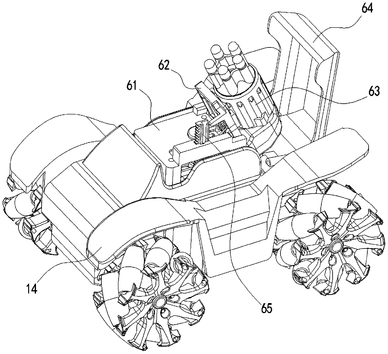
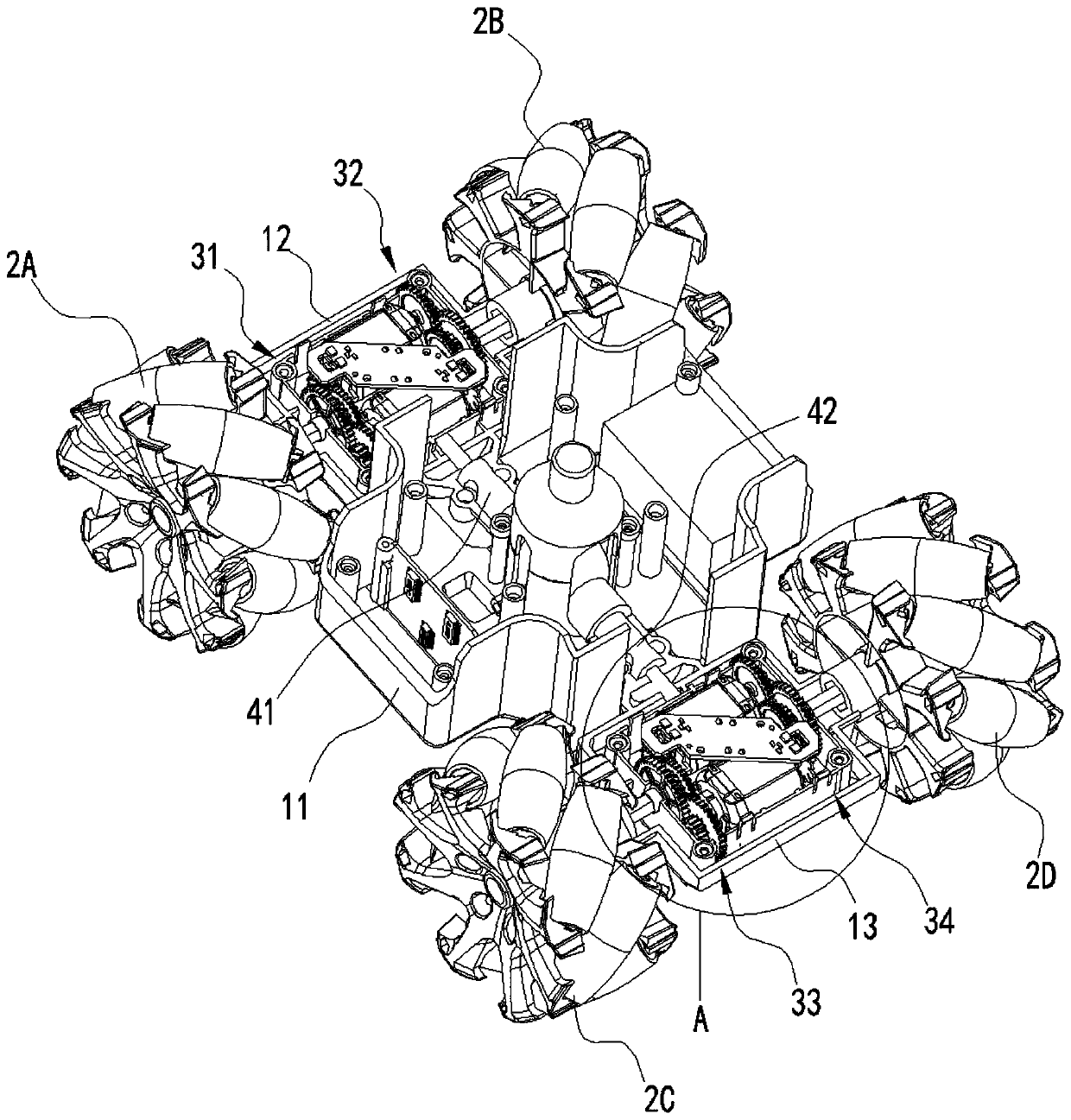
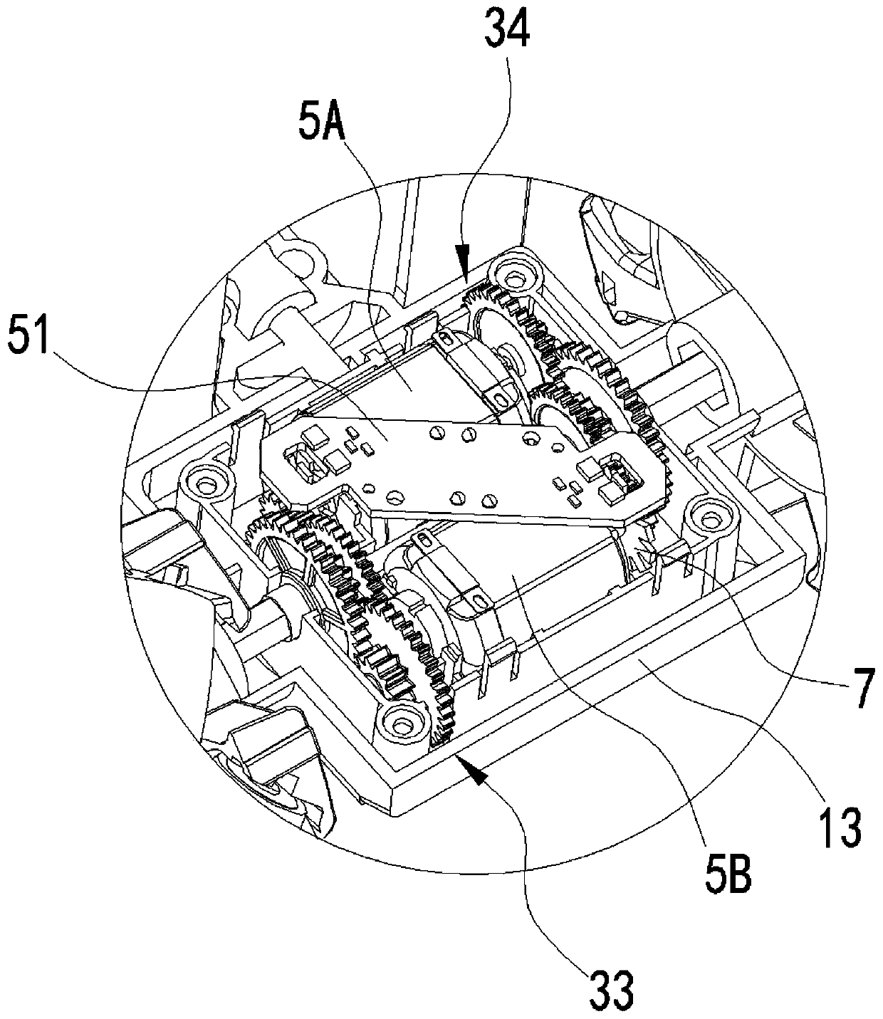
[0045] In order to make the purpose of the present invention, technical solutions and advantages clearer, the following will combine figure 1 - Figure 12 The accompanying drawings describe the present invention in further detail.

[0046] refer to figure 1 - Figure 12 As shown, a remote control car with a simple servo control system includes a vehicle body, a driving wheel that is rotated on the vehicle body, a reduction gear set that is installed in the vehicle body and is connected to the drive wheel, and a reduction gear set that is installed in the vehicle body and connected The motor connected by the transmission, when the motor is energized and rotates at high speed, the linkage reduction gear set rotates, and the reduction gear set converts the rotation of the motor at high speed and low torque into the rotation of low speed and high torque, and then the linkage drive wheel rotates.

[0047] The vehicle body can be an integral fixed vehicle body or a split type veh...


PUM


Abstract

The invention discloses a remote control car with a simple servo control system. The remote control car comprises a car body, wherein driving wheels are rotatably arranged on the car body; a simple coding disc and the driving wheels are arranged in a synchronous rotating manner; when the simple coding disc rotates, a photoelectric receiving tube is continuously switched on and switched off to forma pulse signal; a motor, a remote control receiving unit and the photoelectric receiving tube are electrically connected with a main control unit respectively; the remote control receiving unit receives a command sent by a remote controller and sends the command to the main control unit to converse the command into a desired rotating speed signal which indicates a desired rotating speed of the driving wheels; the pulse signal formed by the photoelectric receiving tube is sent to the main control unit and is conversed into an actual rotating speed signal which indicates an actual rotating speed of the driving wheels; the main control unit calculates a difference value between the desired rotating speed signal and the actual rotating speed signal to drive the motor to increase or decrease the rotating speed, so that the actual rotating speed signal is caused to get close to the desired rotating speed signal. The remote control car can accurately monitor and control the rotating wheel ofthe wheels at lower cost.

Description

technical field [0001] The invention relates to the field of remote control cars, in particular to a remote control car with a simple servo control system. Background technique [0002] Existing low-end remote control cars such as toy remote control cars generally use cheap DC iron core brushed micro motors, such as FF130 motors, which have high speed and low torque, and need to drive the wheels through a reduction gear set to reduce the speed and increase the torque. At the same time, PWM is used to control the motor speed, but the PWM control speed is not accurate, so there is often a gap between the motor speed and the expected speed, especially there is often a large gap between the speeds of different motors, resulting in differences in wheel speed and vehicle body deviation. , jumping and other phenomena; for small remote control vehicles equipped with omnidirectional wheels such as Mecanum wheels, it is necessary to control the speed of each wheel more accurately to a...

Claims


Application Information

Patent Timeline
Patent Type & Authority Applications(China)
IPC IPC(8): A63H17/26A63H17/267A63H17/36
CPCA63H17/26A63H17/36
Inventor 吴根飚
Owner 吴根飚
Why Eureka
Try Eureka