
Method and system for efficient load identification

a load identification and efficient technology, applied in the direction of instrumentation, vehicle tyre testing, measurement of force components, etc., can solve the problems of large and complex transfer-function measurement effort, method has significant mathematical limitations, and prior art approach suffers from certain drawbacks, so as to improve the stability of force estimation

Active Publication Date: 2021-02-16
SIEMENS IND SOFTWARE NV
View PDF10 Cites 0 Cited by
  • Summary
  • Abstract
  • Description
  • Claims
  • Application Information

AI Technical Summary

Benefits of technology

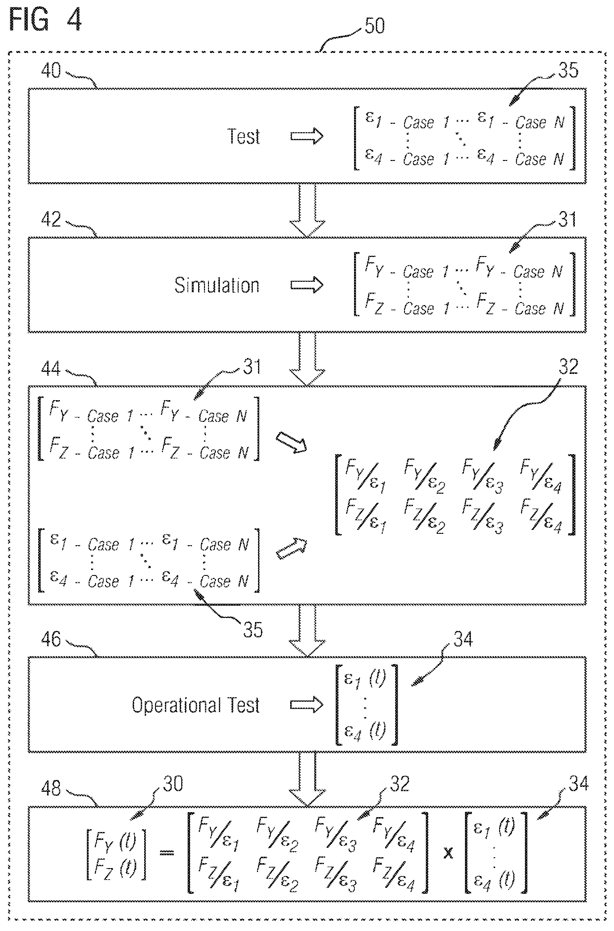
The patent text describes a new method for estimating the forces on a car's body structure or suspension components during operation. This method uses a calibration matrix that is calculated using data from a simulation and a test environment. This calibration matrix is applied to operational strain data from track measurements to estimate the time-domain track forces. This approach results in a stable and accurate force estimation.

Problems solved by technology

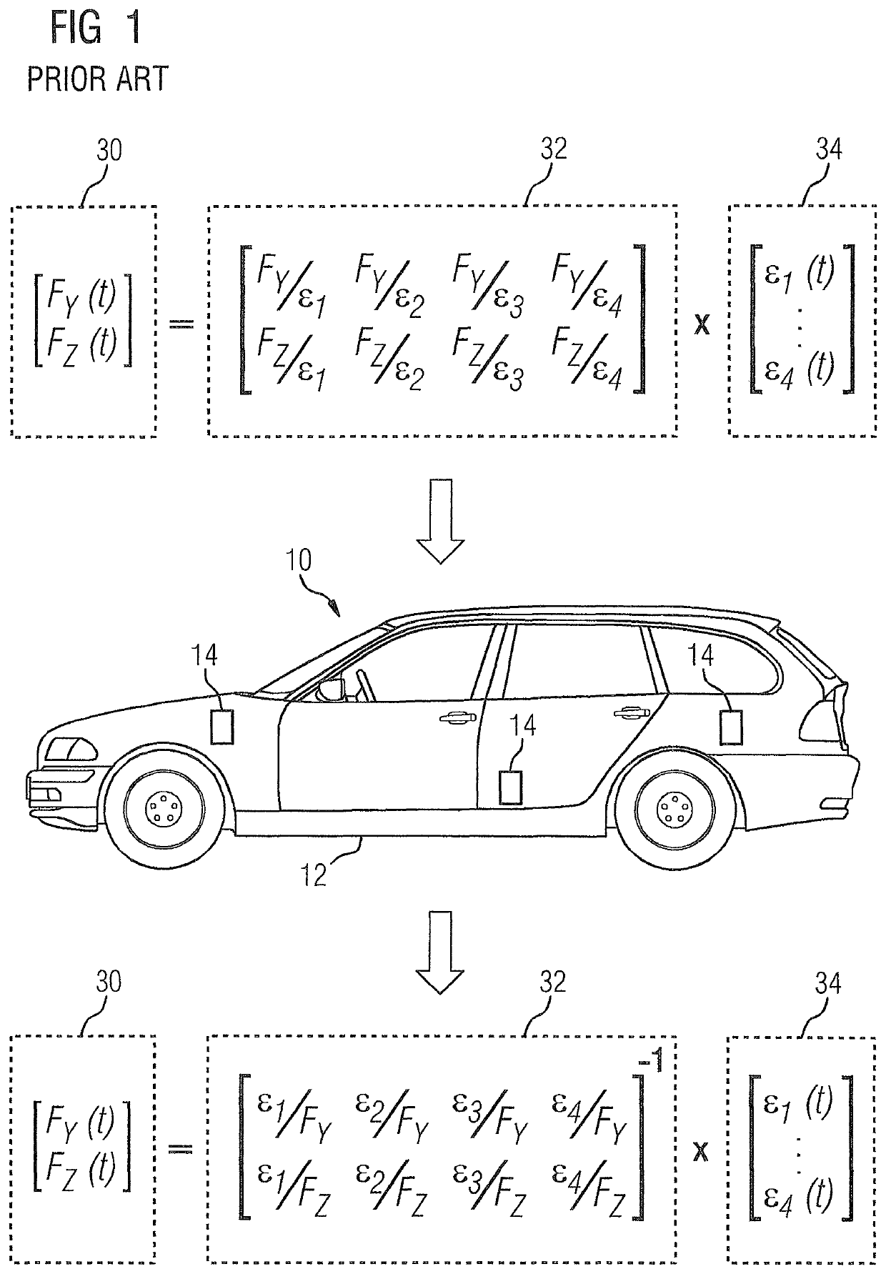
This prior art approach suffers from certain drawbacks.
On the other hand, it involves a large and complex transfer-function measurement effort to identify the calibration matrix.
Furthermore, even with high-channel-count instrumentation and optimized transfer-function measurement approaches, this method has significant mathematical limitations in the case of mechanical structures with a lot of close-by acting body loads, which cannot be identified accurately due to matrix conditioning problems.
Additionally, the calibration matrix needs to be re-measured for each different vehicle body type, giving an extra potential uncertainty on the identified loads as each resulting calibration matrix can have its own limitations related to factors such as conditioning or signal-to-noise ratio.

Method used


Image

  • Method and system for efficient load identification
  • Method and system for efficient load identification
  • Method and system for efficient load identification

Examples


Embodiment Construction

[0027]This disclosure describes a method, a system and a device providing an efficient load identification technique that amongst others can be used for vehicle dynamic performance evaluations. Those skilled in the art will readily understand that the approach proposed here can be applied to various types of vehicles, e.g., passenger cars, sports cars, trucks, and also to parts of such vehicles, e.g., a soft mounted subframe, different suspension components and either the front or the rear axle. Furthermore, those skilled in the art will readily understand that the approach can be used by OEM vehicle producers, test or inspection facilities and / or the racing industry.

[0028]FIG. 1 shows in simplified form the prior art method for identifying loads impacting the body structure 12 of a vehicle 10. To this end, FIG. 1 shows a vehicle 10, comprising a vehicle body structure 12, where a plurality of strain-gauge sensors 14 (only three are shown) is assigned to the body structure 12. It is...


PUM

PropertyMeasurementUnit
vehicle body forcesaaaaaaaaaa
forceaaaaaaaaaa
timeaaaaaaaaaa

Abstract

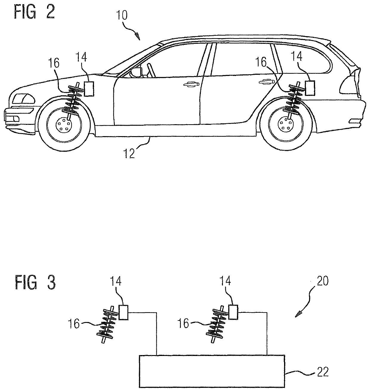
A method, system, apparatus and computer program for identifying loads impacting a vehicle that includes a vehicle body and a suspension system, wherein the method includes acquisition of a system response from a plurality of sensors under dedicated conditions in a test environment, where the said sensors are assigned to the suspension of the vehicle, acquisition of system loads by applying the same dedicated conditions in a simulation environment, generation of a calibration matrix based on data pertaining to the system response and data pertaining to the system loads, acquisition of an operational system response from the plurality of sensors in a test-track situation, and utilization of the acquired operational system response and the calibration matrix for calculating numerical values for the loads impacting the vehicle.

Description

CROSS-REFERENCE TO RELATED APPLICATIONS[0001]This is a U.S. national stage of application No. PCT / EP2016 / 072674 filed Sep. 23, 2016, the content of which is incorporated herein by reference in its entirety.BACKGROUND OF THE INVENTION1. Field of the Invention[0002]The present invention generally relates to a method, system and a device for an advanced load identification technique that enables amongst others vehicle dynamic performance evaluation.2. Description of the Related Art[0003]In-depth vehicle dynamic performance evaluations have as yet been implemented through identification of the time-domain loads acting on a vehicle body structure. Vehicle body structure deformation can be calculated by using these time-domain loads for identifying potential weak spots in the vehicle body design. Furthermore, the transient build-up of each load can be evaluated for different vehicle configurations and / or different vehicle body configurations to understand how changes in suspension or body...

Claims


Application Information

Patent Timeline
Patent Type & Authority Patents(United States)
IPC IPC(8): G01M17/04G06F17/16G01M17/007G01M17/06G01L5/16G01M17/02G06F30/23G06F30/20
CPCG01M17/04G06F17/16G01L5/16G01M17/007G01M17/0072G01M17/0078G01M17/02G01M17/06G06F30/20G06F30/23
Inventor GELUK, THEO
Owner SIEMENS IND SOFTWARE NV
Learn More