AI technical title is built by Patsnap AI team. It summarizes the technical point description of the patent document.
a head and counterweight technology, applied in the direction of gearing, positive displacement liquid engine, borehole/well accessories, etc., can solve the problems of significant unresolved net torque, unbalanced lifting and lowering, and high cost of heavy lifting machines, so as to achieve the effect of adding stability and strength, and adding stability and strength
Active Publication Date: 2021-03-02
DREHER GEORGE R
View PDF3 Cites 0 Cited by
Summary
Abstract
Description
Claims
Application Information
AI Technical Summary
This helps you quickly interpret patents by identifying the three key elements:
Problems solved by technology
Method used
Benefits of technology
Benefits of technology
[0022]In one embodiment, the combination of head weight and crank weight facilitate the increased counterbalance effect required to raise the rods and the decreased counterbalance effect required to lower the rods, due to raising the rods requiring lifting the weight of the rods in fluid plus the weight of the fluid, and lowering the rods requiring only the weight of the rods in fluid. Head with contiguous counterweight increases permissible load, reduces net torque and lowers structural stress and fatigue to allow longer life speed reducers, smaller speed reducers, and longer reciprocating vertical stroke length which are economic and performance benefits.
[0036]A larger outer diameter of the head area for running the flexible connector to the downhole rods relative to the upper pitman bearing increases the stroke length.
Problems solved by technology
Machines designed to do heavy lifting are big and expensive and repairs on worn parts are expensive.
One problem is that in beam pumped wells the lifted weight is about 1.5 times the weight of the lowered weight due to lifting the weight of the fluid plus the buoyant weight of the sucker rods in the pipe when lifting, but the fluid weight is then held by the downhole pump standing valve when lowered making lifting and lowering unbalanced, so in known references, the difference in counterweight required is split on the up stroke and down stroke which leaves significant unresolved net torque due to the unsolved unbalanced downhole condition.
But, the air balance design can reverse direction and the gear teeth in the speed reducer are known for long life.
All the designs mentioned can achieve a fairly limited increase in efficiency but still leave the problem of downhole unbalanced weight between lifting and lowering.
Method used
Image
Click on the blue label to locate the original text in one second.
Reading with bidirectional positioning of images and text.
Examples
Embodiment Construction
[0019]Embodiments of the present invention relate to lifting and lowering an unbalanced load with a head contiguous with a counterweight having a fulcrum and connected to a load and an effort.
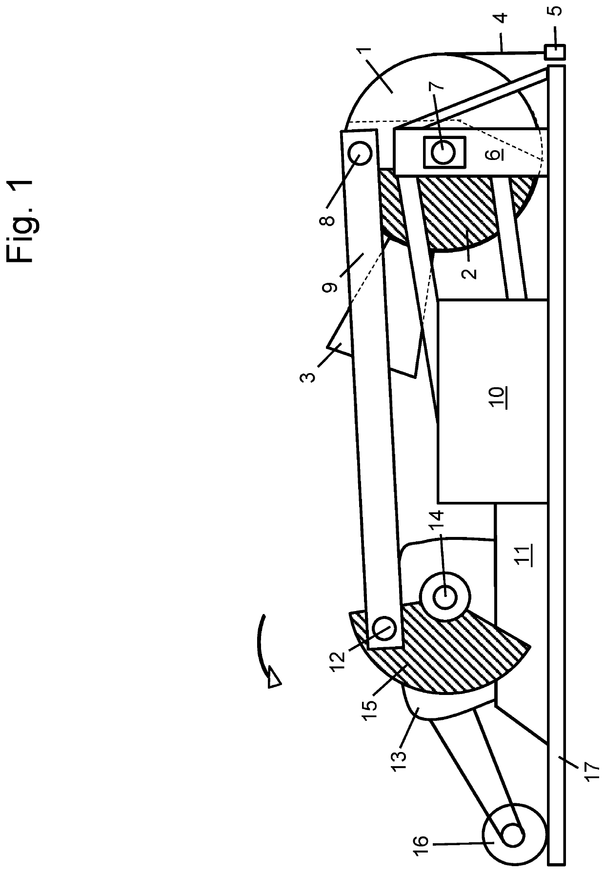
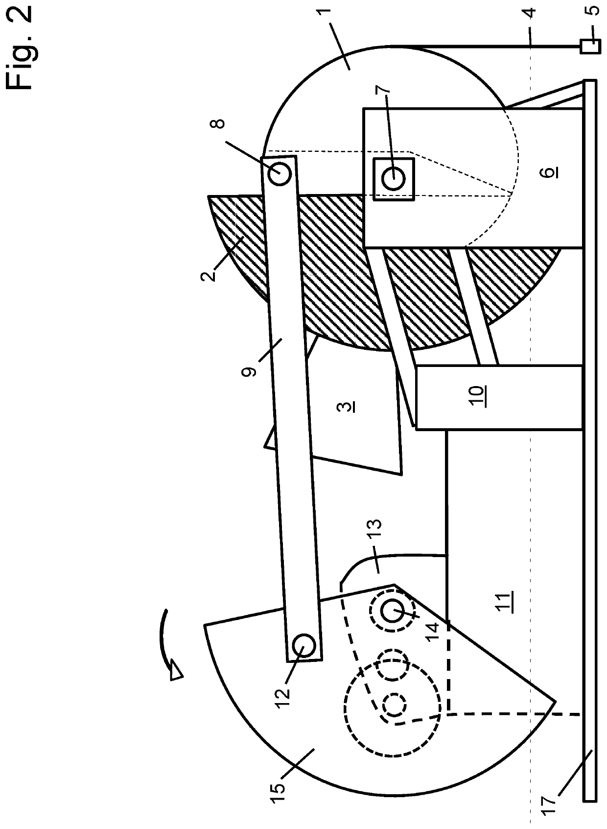
[0020]In one embodiment, a sucker rod pumping unit, the lifting and lowering of the well load can be caused by the reciprocating motion of a head tipping on a fulcrum and counterbalanced with an counterweight contiguous to the head.
[0021]In one embodiment, when maximum counterweight effect for lifting the unbalanced well load is needed, which occurs at the same time as lowering the crank arm, the head's counterweight is oscillated by linkages, timed for maximum offsetting of the well load. Vice versa, when minimum counterbalance effect for lowering the well load is desired, which occurs at the same time as raising the crank arm, the head's counterweight is oscillated by linkages, timed for minimum offsetting of the well load.
[0022]In one embodiment, the combination of head weight and crank weig...
PUM
Abstract
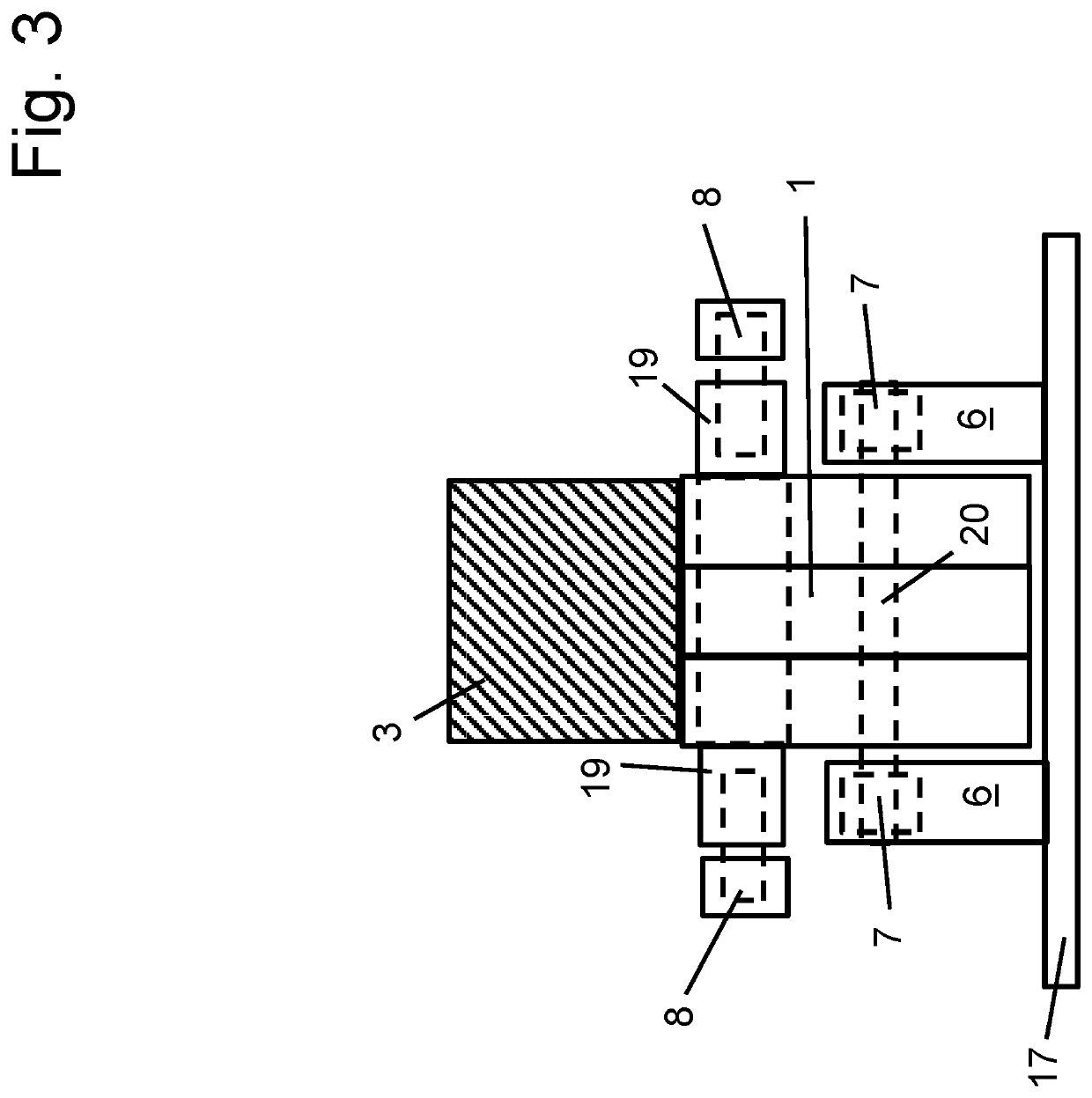
A prime example of an application for a head with contiguous counterweight is a sucker rod reciprocating pump whose circular arc head is contiguous with a counterweight and is pivotably connected to the pitman arm, crank arm weight, and speed reducer. The pitman arm is substantially horizontal and the crank arm to wrist pin phase angle is about 70-90 degrees. Auxiliary counter weight extends from the head weight on a stinger and the head weights are adjustable. The head weight diameter is either constrained within the circular arc head's outer diameter or can be larger. The upper pitman bearings are outboard on the equalizer which is integral with the head. The center bearing of the head is outboard on the rectangular sampson post. The head counterweight increases permissible load on a speed reducer. This example use of a head with contiguous counterweight has can be configured to utilize beneficial embodiments for adjusting sampson post height and pitman arm length; and for changing the stroke length without removing the wrist pin from the crank weight hole.
Description
CROSS-REFERENCE TO RELATED APPLICATIONS[0001]This is a division application Ser. No. 16 / 130,068, Filed Sep. 13, 2018, Granted on Sep. 13, 2018.[0002]This application claims priority to and the benefit of the filing of U.S. Provisional Patent Application No. 62 / 411,556, filed on Oct. 22, 2016; U.S. Provisional Patent Application No. 62 / 403,165, filed on Oct. 2, 2016; U.S. Provisional Patent Application No. 62 / 421,410, filed on Nov. 14, 2016; U.S. Provisional Patent Application Ser. No. 62 / 426,337, filed on Nov. 25, 2016; U.S. Provisional Patent Application Ser. No. 62 / 535,846, filed on Jul. 22, 2017; U.S. Provisional Patent Application Ser. No. 62 / 535,945, filed on Jul. 23, 2017; and U.S. Non-Provisional patent application Ser. No. 15 / 719,964, filed on Sep. 29, 2017; U.S. Non-Provisional patent application Ser. No. 15 / 789,760, filed on Oct. 20, 2017; U.S. Non-Provisional patent application Ser. No. 15 / 810,083, filed on Nov. 12, 2017; U.S. Non-Provisional patent application Ser. No. 1...
Claims
Application Information
Patent Timeline
Application Date:The date an application was filed.
Publication Date:The date a patent or application was officially published.
First Publication Date:The earliest publication date of a patent with the same application number.
Issue Date:Publication date of the patent grant document.
PCT Entry Date:The Entry date of PCT National Phase.
Estimated Expiry Date:The statutory expiry date of a patent right according to the Patent Law, and it is the longest term of protection that the patent right can achieve without the termination of the patent right due to other reasons(Term extension factor has been taken into account ).
Invalid Date:Actual expiry date is based on effective date or publication date of legal transaction data of invalid patent.

