Honeycomb structure

a honeycomb and structure technology, applied in the field of honeycomb structure, can solve the problems of inability to suppress the flow of exhaust gas, and the purification performance cannot be lowered, so as to improve the purification performance and increase the geometric surface area of partition walls

Active Publication Date: 2021-03-23
NGK INSULATORS LTD
View PDF12 Cites 0 Cited by
  • Summary
  • Abstract
  • Description
  • Claims
  • Application Information

AI Technical Summary

Benefits of technology

[0006]In the honeycomb structure of Patent Document 1, the geometric surface area of the partition wall can be increased by the fins disposed on the partition wall. However, in the honeycomb structure of Patent Document 1, a flow of the exhaust gas tends to be stagnated between two adjacent fins, which is, in particular, a factor of lowering contact property with the catalyst at the high flow rate (specifically, space velocity of about 8,300 / hour or more). In particular, in the honeycomb structure of Patent Document 1, it is preferable that the same number of fins is disposed on each side configuring the cell. In this case, there is a problem in that the stagnation of the flow of the exhaust gas is very likely to occur and the purification performance cannot be suppressed from being lowered when the flow rate is large.
[0007]The present invention has been made considering the problems of the prior art. An object of the present invention is to provide a honeycomb structure in which purification performance is improved when a flow rate of exhaust gas is large and abrasion resistance is maintained, when a catalyst is loaded.
[0016]According to a third aspect of the present invention, the honeycomb structure of the first or second aspects is provided, wherein in the cross section orthogonal to the extending direction of the cells, the plurality of specific cells are arranged in one direction, and in the one direction, variation in the disposition direction of the shape of the cell including the protrusion has regularity.
[0018]Since the honeycomb structure of the present invention has the protrusions provided to protrude into the cells, the geometric surface area of the partition walls can be increased by the protrusion. In particular, the honeycomb structure of the present invention can hardly cause the stagnation of the flow of the exhaust gas even when the flow rate of the exhaust gas is large (at the high flow rate) and improve the purification performance when being used as the catalyst carrier. The honeycomb structure of the present invention maintains the abrasion resistance.

Problems solved by technology

In this case, there is a problem in that the stagnation of the flow of the exhaust gas is very likely to occur and the purification performance cannot be suppressed from being lowered when the flow rate is large.

Method used


Image

  • Honeycomb structure
  • Honeycomb structure
  • Honeycomb structure

Examples


example 1

[0081]In Example 1, first, the forming raw material for manufacturing the honeycomb structure was prepared. Specifically, the forming raw material was prepared by adding a binder, a surfactant, a pore former, and water to a ceramic raw material. As the ceramic raw material, kaolin, talc, and alumina which are the cordierite forming raw material was used.

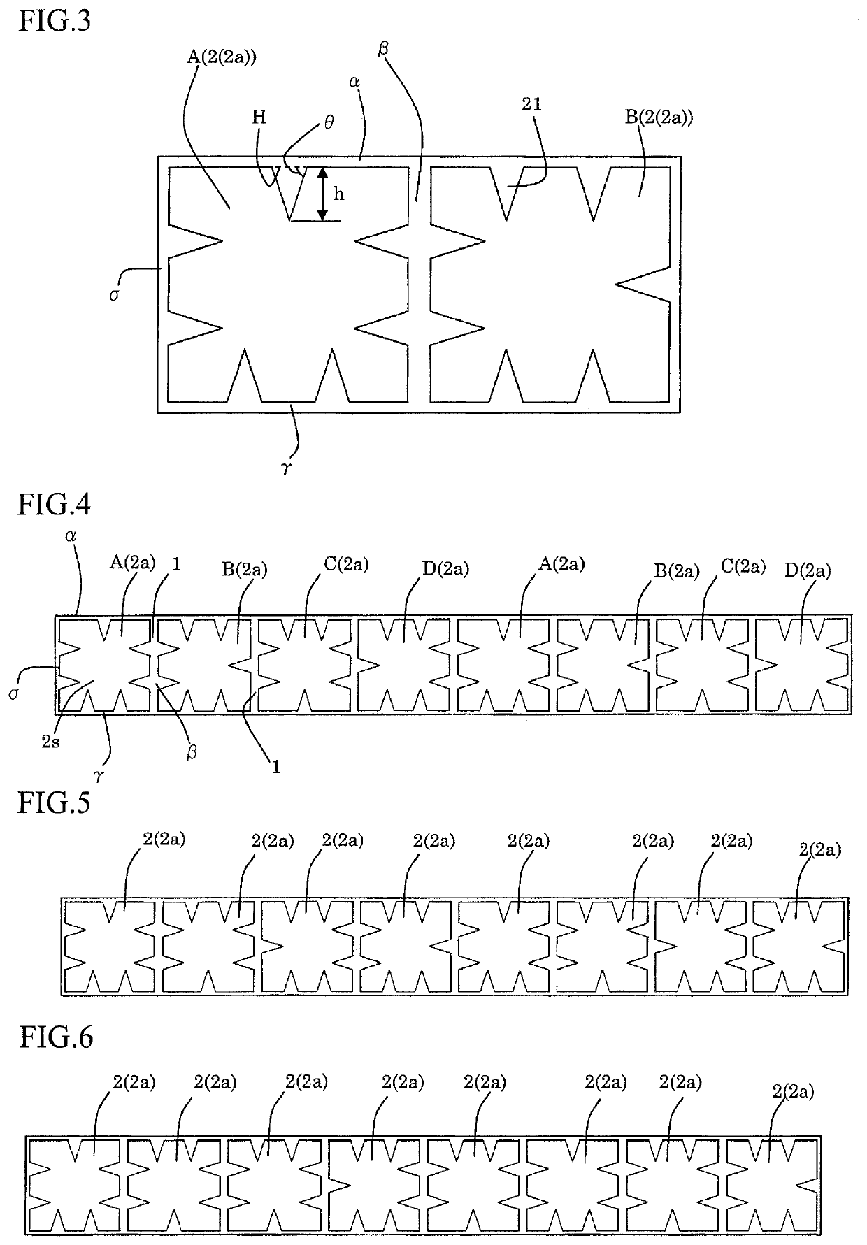
[0082]Next, the obtained forming raw material was kneaded with the kneader and then pug-milled in the vacuum pugmill to form the kneaded material. Next, the obtained kneaded material was extruded using the die to manufacture the honeycomb formed body. The die used the fact that the variations in the disposition directions of the shapes of the cells including the protrusions become “the shape of cell of one specific cell is the 4-fold rotational symmetry of the shapes of the cells of other specific cells adjacent to one specific cell” as shown in FIG. 4. In the honeycomb formed body, after the firing, the thickness of the partition wa...

examples 2 to 18

, Comparative Examples 1 to 7

[0114]As shown in the above Table 1 and the following Table 3, the honeycomb structure was manufactured in the same manner as in Example 1 except that it was manufactured to have a predetermined number of protrusions and the variations in the disposition directions of the shapes of the cells including the protrusions.

[0115]Even for the honeycomb structures of Examples 2 to 18 and Comparative Examples 1 to 7, the thickness (mm) of the partition wall, the porosity (%) of the partition walls, and the cell density (cell / cm2) were measured in the same manner as in Example 1, and the LA-4 test, the erosion test and the evaluation on the pressure loss were performed. The results are shown in the above Tables 1 and 2 and the following Tables 3 and 4.

[0116]

TABLE 3ThicknessofCellCellThe number ofVariationRatio ofpartitiondensitydensityprotrusions [number]inspecificwall[cell / [cell / PorositySideSideSideSideSideSideCelldispositioncell[mm]inch2]cm2][%]123456shapedirect...


PUM

PropertyMeasurementUnit
angleaaaaaaaaaa
angleaaaaaaaaaa
thicknessaaaaaaaaaa

Abstract

A honeycomb structure, including: a honeycomb structure body having a porous partition walls which are disposed to define a plurality of cells and a circumferential wall, wherein the partition walls are provided with protrusions which protrude to extend into the cells and are continuously disposed in an extending direction of the cells, the cells have a polygonal shape in a cross section orthogonal to the extending direction of the cells, the plurality of cells include a plurality of specific cells having at least one place where two sides each of which is provided with a different number of protrusions intersect each other, and in the cross section orthogonal to the extending direction of the cells, disposition directions of the shapes of the cells including the protrusions in the specific cells are different in one specific cell and other specific cells other than the one specific cell.

Description

[0001]The present application is an application based on JP-2017-068342 filed on Mar. 3, 2017 with the Japan Patent Office, the entire contents of which are incorporated herein by reference.BACKGROUND OF THE INVENTIONField of the Invention[0002]The present invention relates to a honeycomb structure. More particularly, the present invention relates to a honeycomb structure in which purification performance is improved when a flow rate of exhaust gas is large (high flow rate) and abrasion resistance is maintained.Description of the Related Art[0003]In recent years, awareness of environmental problems has been increasing in society as a whole. For this reason, in the field of technologies to burn fuel to generate power, various technologies for removing harmful components such as nitrogen oxides from the exhaust gas generated during combustion of fuel have been developed. As various technologies for removing the harmful components, for example, various technologies for removing harmful...

Claims


Application Information

Patent Timeline
Patent Type & Authority Patents(United States)
IPC IPC(8): B01D46/24B01J35/04F01N3/10C04B35/185C04B35/478C04B35/80C04B38/00C04B35/195C04B35/565F01N3/28
CPCB01J35/04B01D46/247B01D46/2429B01D46/2474C04B35/185C04B35/195C04B35/478C04B35/565C04B35/806C04B38/0006C04B38/0009F01N3/10F01N3/2828B01D2046/2433B01D2046/2481B01D2046/2492C04B2235/663F01N2260/06F01N2260/14F01N2330/06F01N2330/34F01N2330/38F01N2510/06B01J32/00B01D53/9431B01D46/2486B01D46/2476C04B35/80C04B35/515
Inventor AOKI, YOICHI
Owner NGK INSULATORS LTD
Why Eureka
Try Eureka