Bistable actuator device having a shape memory element

a technology of bistable actuators and shape memory wires, which is applied in the direction of limiting/preventing/returning movement of parts, controlling members, instruments, etc., can solve the problems of large construction space required, critical stresses, and accelerated aging of shape memory wires

Active Publication Date: 2021-03-23
UNIV DES SAARLANDES +1
View PDF17 Cites 0 Cited by
  • Summary
  • Abstract
  • Description
  • Claims
  • Application Information

AI Technical Summary

Benefits of technology

[0015]Such an actuator device has the advantage that it can be used to provide bistable / multistable actuator positions that can only be achieved by exerting pulling forces. The pulling forces can be easily provided by shape memory wires. In particular, such an actuator device can be realized without restoring spring forces or weight forces.
[0021]This allows the actuator elements to be located at pull points on the bending element, eliminating the need for additional components to convert pulling forces into switching torques. In particular, it can be achieved simultaneously that the pulling forces of the actuator elements are exerted in the same direction for switching between the actuator positions. This enables a space-saving design of the actuator device, whereby the two actuator elements can be arranged essentially parallel to each other.
[0023]By arranging the pull points relatively close to the attachment point at which the bending element is pivotally mounted, a high switching torque for bistable deformation of the bending element can be triggered by a small actuator stroke, so that it is possible to use relatively short shape memory wires with a small stroke as the actuator element. This also allows such an actuator device to be as compact as possible, since the length of the shape memory wire can be considerably reduced compared to known shape memory actuators.

Problems solved by technology

If the actuator device is to be held in this position for a longer period of time, this can be very energy-intensive as the higher temperature of the shape memory wire needs to be maintained.
With such an actuator device, the restoring force of the return spring acts permanently on the shape memory wire; this can lead to critical stresses and accelerated aging of the shape memory wire due to the permanent load.
Furthermore, a large construction space is required to achieve appreciable deflections by the shape memory wire, as the achievable deflection depends on the length of the shape memory wire.

Method used


Image

  • Bistable actuator device having a shape memory element
  • Bistable actuator device having a shape memory element
  • Bistable actuator device having a shape memory element

Examples


Embodiment Construction

[0008]This object has been achieved by the actuator device according to claim 1 and the method for operating an actuator device according to the further independent claim.

[0009]Further embodiments are specified in the dependent claims.

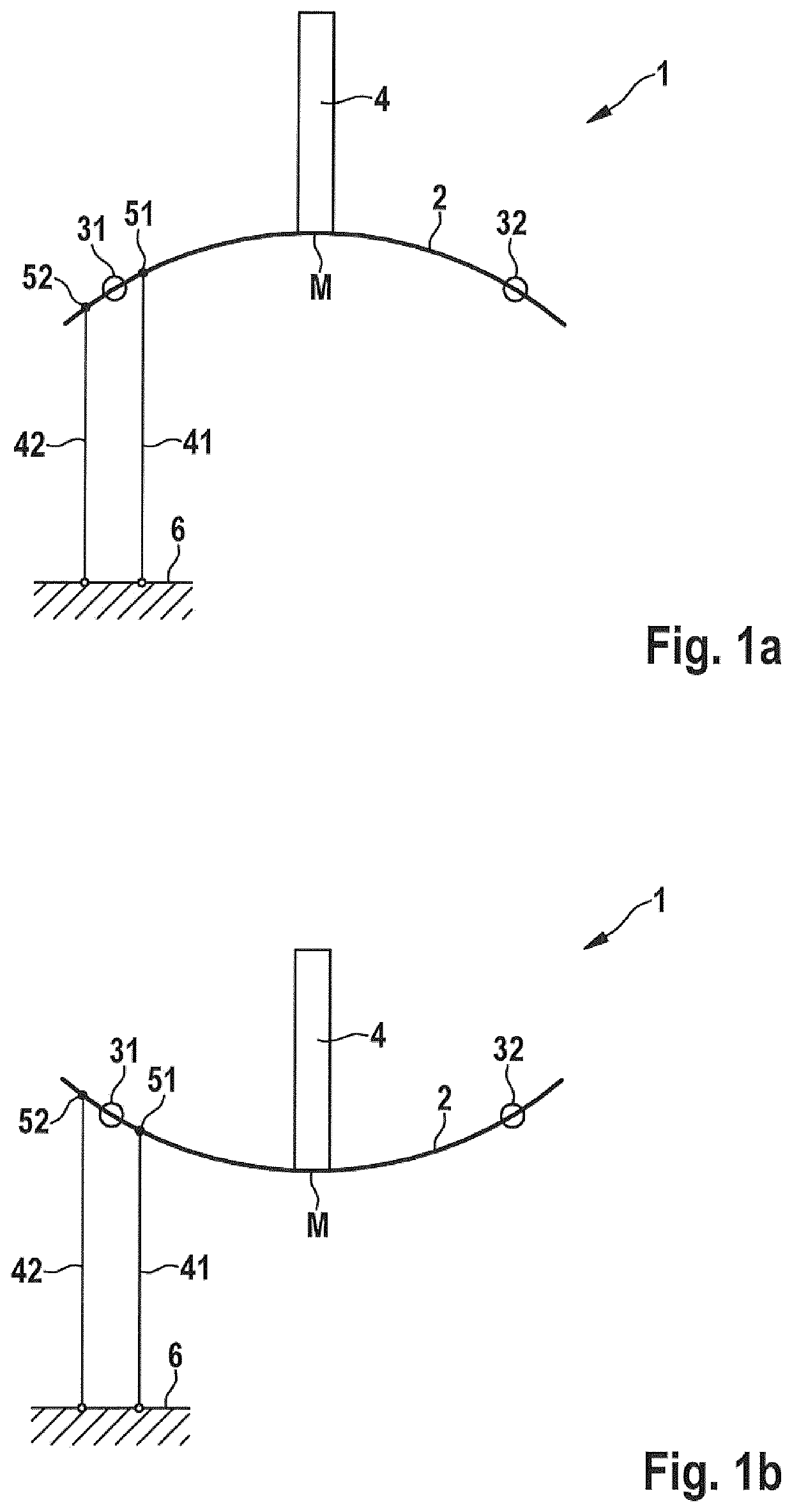
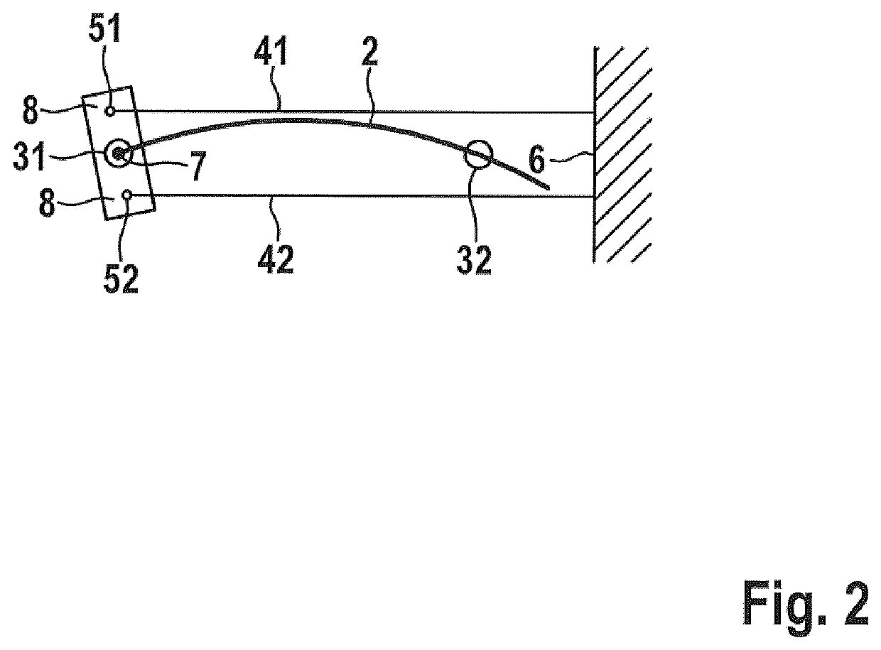
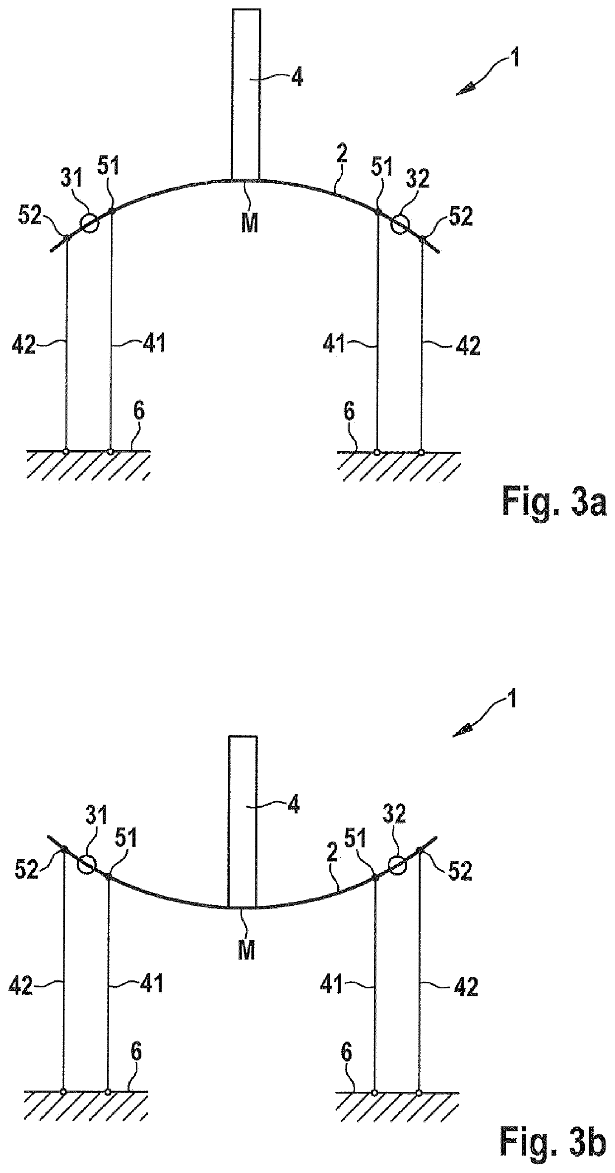
[0010]According to a first aspect, an actuator device is provided at least two actuator positions; comprehensive:[0011]a bistable elastic bending element held at at least one attachment point such that, by applying a switching torque at the attachment point, elastic deformation of the bending element results in a change from a first actuator position to a second actuator position each representing a bistable position of the bending element;[0012]at least one actuator element formed with a shape memory wire, wherein the shape memory wire causes a pulling force by heating and is coupled to a portion of the bending element at the attachment point such that the pulling force causes the switching torque at the attachment point to move the bending element fr...


PUM


Abstract

The invention relates to a bistable actuator device (1) for providing at least two actuator positions comprising:an elastic bending element (2) supported at at least one attachment point (31, 32, 34) such that, by applying a switching torque at the attachment point (31, 32, 34), elastic deformation of the bending element (2) results in a change from a first actuator position to a second actuator position; andat least one actuator element (41, 42) formed with a shape memory wire, the shape memory wire causing a pulling force by heating and being coupled to a portion of the bending element (2) at the attachment point (31, 32, 34) so that the pulling force causes the switching torque at the attachment point (31, 32, 34) to move the bending element (2) from the first actuator position to the second actuator position.

Description

TECHNICAL FIELD[0001]The invention relates to actuator devices, in particular an actuator device with a bistable element which can be brought into a changed bistable state with respect to its shape, orientation and / or position by deformation of an actuator element made of a shape memory material.TECHNICAL BACKGROUND[0002]Shape memory materials are already used in many ways for actuator devices. In particular, many actuator devices use a force resulting from the length reduction of a previously stretched wire made of shape memory material (shape memory wire) when exposed to heat. For such wires, however, there must always be a restoring force in order to stretch the wire, which has been shortened by thermal activation, back to its previous length. This is often done by a spring force, by the force of an activated additional shape memory wire or by a weight force of a mass.[0003]In particular in actuator devices with a shape memory wire as actuator element and with a return spring, a ...

Claims


Application Information

Patent Timeline
Patent Type & Authority Patents(United States)
IPC IPC(8): G05G1/02F03G7/06G05G5/06
CPCF03G7/065G05G1/02G05G5/06
Inventor MOTZKI, PAULSEELECKE, STEFAN
Owner UNIV DES SAARLANDES
Why Eureka
Try Eureka