Supercharge Your Innovation With Domain-Expert AI Agents!

Apparatuses, systems, and methods for improved sensor devices

a sensor device and sensor technology, applied in the field of sensor devices, can solve the problems of vibrational load, strain on the sensor system, etc., and achieve the effect of improving the operation of the sensor device and reducing the linearity error of the sensor devi

Active Publication Date: 2021-03-23
HONEYWELL INT INC
View PDF6 Cites 0 Cited by
  • Summary
  • Abstract
  • Description
  • Claims
  • Application Information

AI Technical Summary

Benefits of technology

[0003]Systems, apparatuses, and methods are disclosed herein for providing improved sensor device operation. An example sensor device may include a bobbin tube that defines a hollow interior configured to receive a probe assembly inserted therein. The device may include a primary coil element wound around the bobbin tube configured to, in response to a current input, generate a primary magnetic flux and may include a secondary coil element wound around the primary coil element. In an instance in which the bobbin tube receives a probe assembly therein, magnetic interaction between the probe assembly and the primary coil element may induce a signal in the secondary coil element. Furthermore, a pitch of the secondary coil element may vary according to a non-linear, polynomial function along a second length of the bobbin tube so as to reduce linearity error of the sensor device.
[0005]In other embodiments, the secondary coil element may further define a plurality of winding sections where the pitch of each winding section of the secondary coil element varies according to the non-linear, polynomial function along its respective length of the bobbin tube. In such an embodiment, the secondary coil element may further define a plurality of coil transition portions between winding sections. Each coil transition portion may be configured to minimize pitch variability between adjacent winding sections.

Problems solved by technology

In these applications, such as in an engine control system, the sensor system may be exposed to strain, vibrational loads, or other forces that may damage the sensor system.

Method used


Image

  • Apparatuses, systems, and methods for improved sensor devices
  • Apparatuses, systems, and methods for improved sensor devices
  • Apparatuses, systems, and methods for improved sensor devices

Examples


Embodiment Construction

Overview

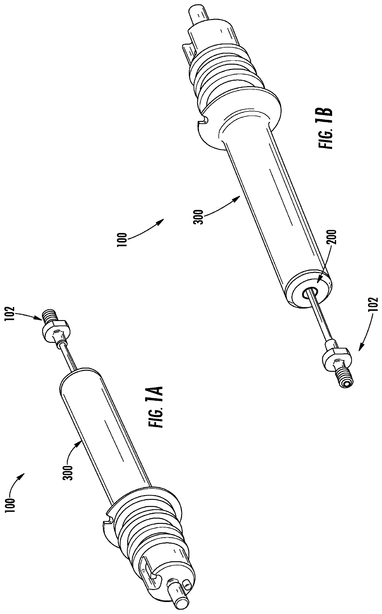
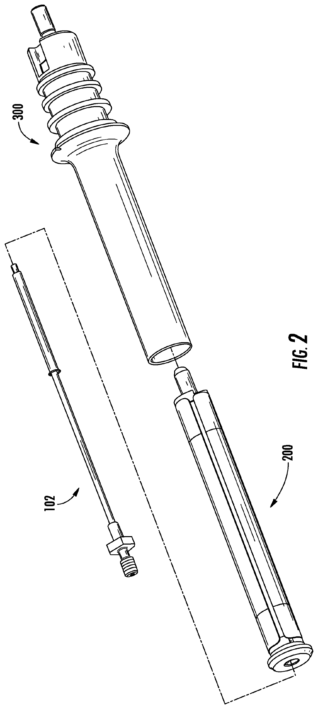
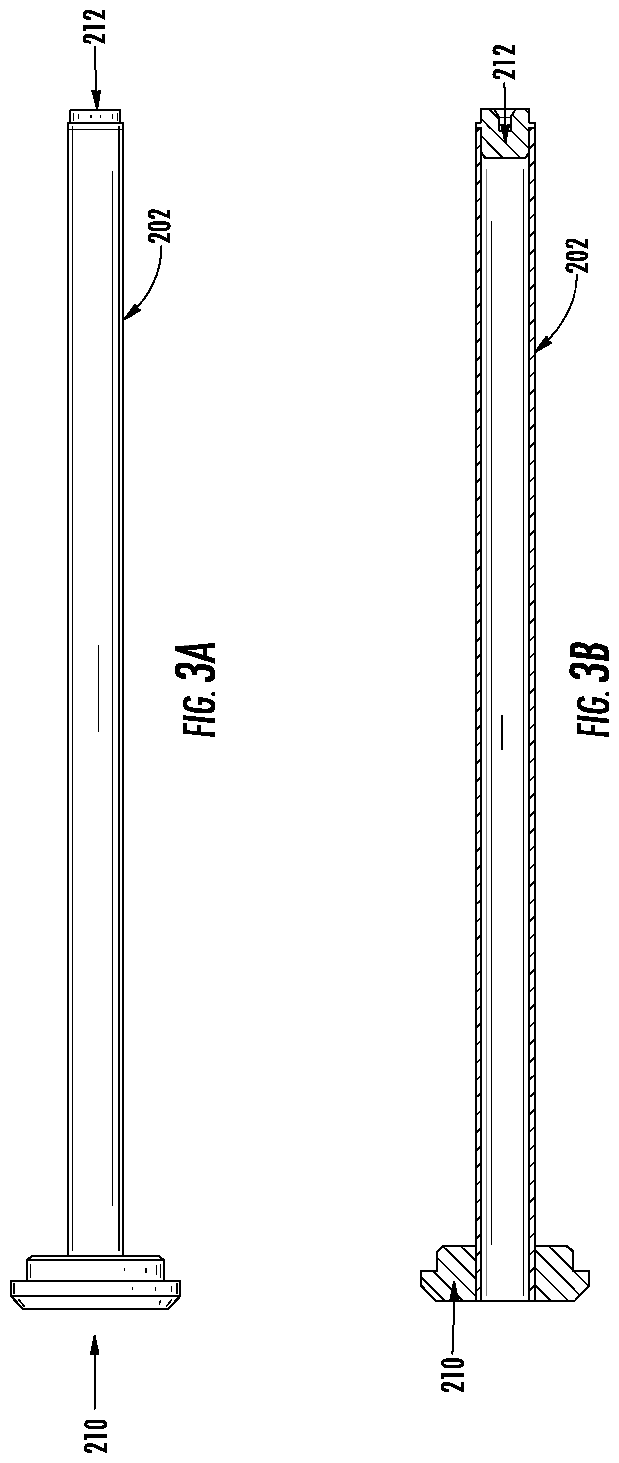
[0020]The present invention now will be described more fully hereinafter with reference to the accompanying drawings in which some but not all embodiments of the inventions are shown. Indeed, these inventions may be embodied in many different forms and should not be construed as limited to the embodiments set forth herein; rather, these embodiments are provided so that this disclosure will satisfy applicable legal requirements. Like numbers refer to like elements throughout. As used herein, terms such as “front,”“rear,”“top,” etc. are used for explanatory purposes in the examples provided below to describe the relative position of certain components or portions of components. Furthermore, as would be evident to one of ordinary skill in the art in light of the present disclosure, the terms “substantially” and “approximately” indicate that the referenced element or associated description is accurate to within applicable engineering tolerances.

[0021]The sensor assembly and sens...


PUM

PropertyMeasurementUnit
magnetic fluxaaaaaaaaaa
lengthaaaaaaaaaa
currentaaaaaaaaaa

Abstract

Apparatuses, systems, and associated methods of assembly are described that provide for improved sensor devices. An example sensor device includes a bobbin tube that defines a hollow interior. The device includes a primary coil element wound around the bobbin tube configured to, in response to a current input, generate a primary magnetic flux and includes a secondary coil element wound around the primary coil element. In an instance in which the bobbin tube receives a probe assembly therein, magnetic interaction between the probe assembly and the primary coil element is configured to induce a signal in the secondary coil element. Furthermore, a pitch of the secondary coil element varies according to a non-linear, polynomial function along a second length of the bobbin tube so as to reduce linearity error of the sensor device.

Description

TECHNOLOGICAL FIELD[0001]Example embodiments of the present invention relate generally to sensor assemblies and, more particularly, to improving the operation of sensor devices.BACKGROUND[0002]Sensor assemblies, such as a Linear Variable Differential Transformer (LVDT), may be used to convert between mechanical motion (e.g., vibration, strain, force, linear motion, etc.) and electrical signals (e.g., current, voltage, etc.). These sensors may be used in hydraulic applications, engine systems, automated teller machines (ATMs), aerospace applications, and a variety of other environments in which conversion between mechanical motion and electrical signals is needed. In these applications, such as in an engine control system, the sensor system may be exposed to strain, vibrational loads, or other forces that may damage the sensor system.BRIEF SUMMARY[0003]Systems, apparatuses, and methods are disclosed herein for providing improved sensor device operation. An example sensor device may i...

Claims


Application Information

Patent Timeline
Patent Type & Authority Patents(United States)
IPC IPC(8): G01D5/22G01D5/20H01F21/06H01F27/32
CPCG01D5/2291G01D5/204H01F21/06H01F27/325G01D5/2046
Inventor ESAKKI, SUBRAMANIANDANIELS, AARONARAGANJI, VIJAYSHEKHAR
Owner HONEYWELL INT INC
Features
  • R&D
  • Intellectual Property
  • Life Sciences
  • Materials
  • Tech Scout
  • Unparalleled Data Quality
  • Higher Quality Content
  • 60% Fewer Hallucinations
Learn More