
Implantable vein frame

a vein frame and implant technology, applied in the field of implantable vein frames, can solve the problems of reduced patient mobility and skin ulceration, non-rigid structures, unintended implant migration, and a number of deficiencies

Active Publication Date: 2021-03-30
ENVVENO MEDICAL CORP
View PDF16 Cites 3 Cited by
  • Summary
  • Abstract
  • Description
  • Claims
  • Application Information

AI Technical Summary

Benefits of technology

The vein frame effectively secures implants within the vein, reducing the risk of migration and neointimal proliferation by providing robust structural support without the need for expansion, thus enhancing venous integrity and circulation.

Problems solved by technology

For example, conditions such as chronic venous insufficient (CVI) or venous reflux may result in significant pain, itching, and swelling, which may consequently give rise to reduced patient mobility and skin ulcerations.
These non-rigid structures, however, suffer from a number of deficiencies.
For example, there may be a risk of failure of the non-rigid structure supporting the implant to expand and / or anchor properly within the vein, which may lead to unintended migration of the implant.
The expansion mechanisms themselves may also represent points of structural weakness that would eventually fail, as those mechanisms may necessarily be less sturdy than the other portions of the implant or support structure for the implant.
Further, the expansion mechanisms of such non-rigid support structures may be more susceptible to failure via neointimal proliferation and overgrowth, as they may be required to be formed of more flexible material more prone to applying radial force to the vein, thus increasing the response of neointimal growth

Method used


Image

  • Implantable vein frame
  • Implantable vein frame
  • Implantable vein frame

Examples


Embodiment Construction

[0027]According to various aspects of the present disclosure, an improved implantable vein frame is contemplated, the improved implantable vein frame being designed to be secured within or interposed between a section or sections of a vein so as to provide structural support to implants which may be placed within the vein.

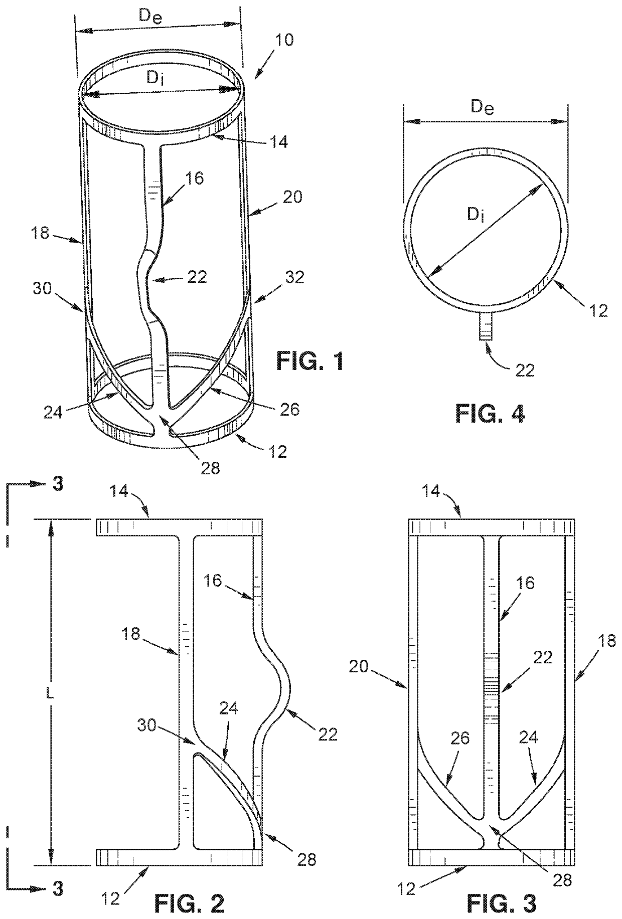
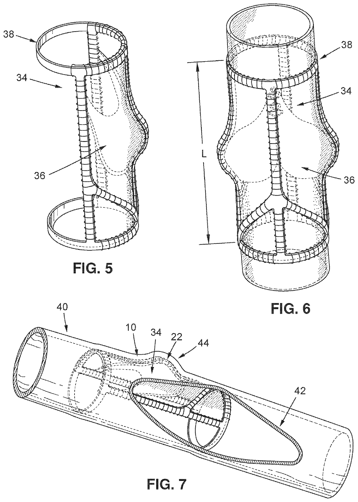
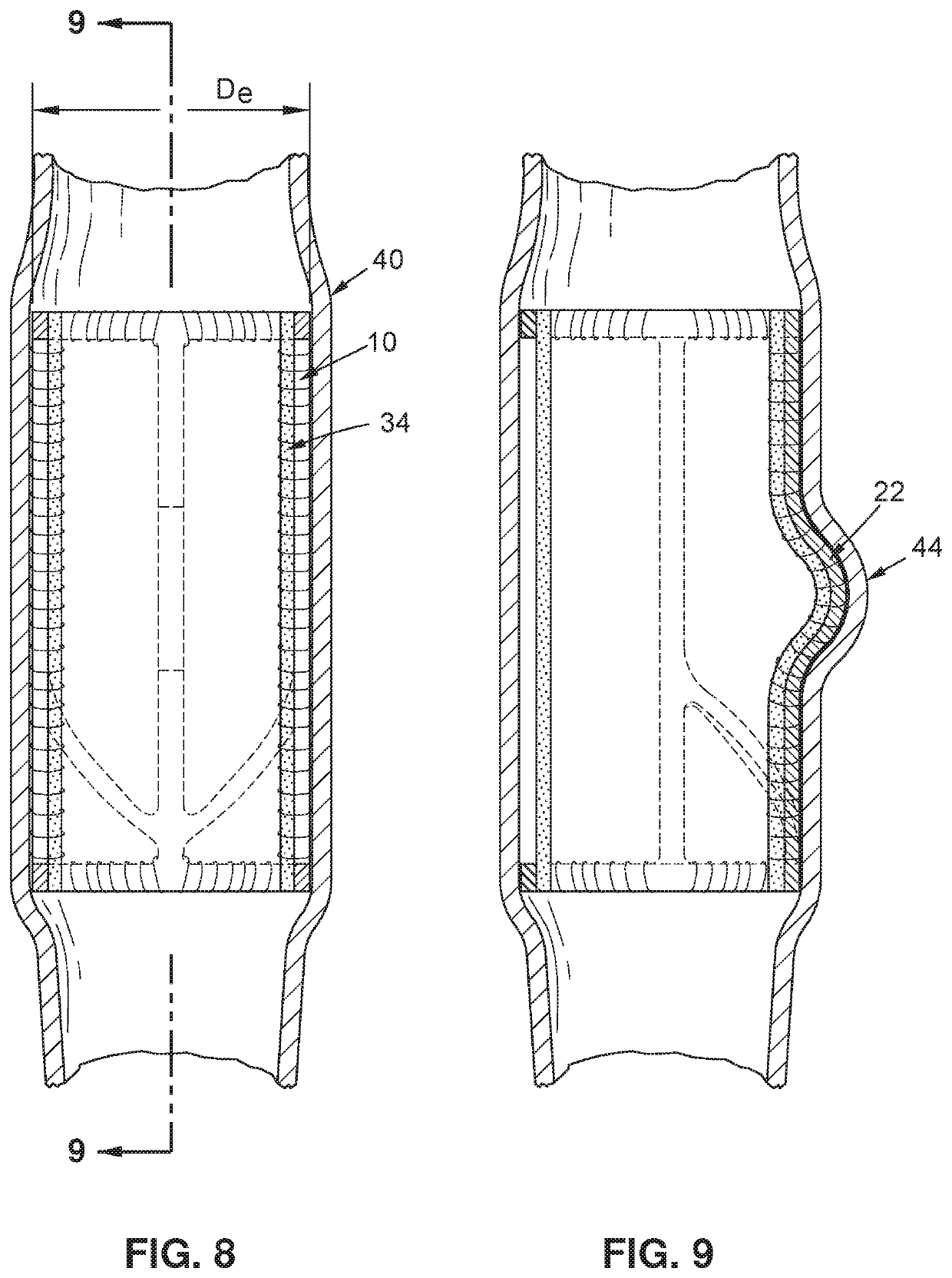
[0028]Turning now to FIG. 1, an exemplary embodiment of a vein frame 10 may be seen. A vein frame 10 of the exemplary embodiment may comprise a first ring member 12 and a second ring member 14, the two ring members being rigidly interconnected by a first interconnecting member 16, a second interconnecting member 18, and a third interconnecting member 20. The first interconnecting member 16 may have a protruding region 22, the first interconnecting member 16 may be interconnected with the second interconnecting member 18 via a first strut member 24, and the first interconnecting member 16 may be interconnected with the third interconnecting member 20 via a second st...


PUM

PropertyMeasurementUnit
diameteraaaaaaaaaa
diametersaaaaaaaaaa
volumeaaaaaaaaaa

Abstract

An implantable vein frame is contemplated in which two ring members are rigidly joined in spaced axial alignment via one or more interconnecting members. One of the one or more interconnecting members defines a protruding region that acts upon the implant placed within the frame and / or the vein that the vein frame is placed within to define a sinus region. The implant is placed within and scaffolded by the vein frame, and the vein frame is subsequently inserted within a vein via a venotomy, or interposed between two vein segments via vein interposition graft. The vein frame acts to support the structural integrity of the implant, and to scaffold and anchor the implant in place with the vein.

Description

CROSS-REFERENCE TO RELATED APPLICATIONS[0001]This application relates to and claims the benefit of U.S. Provisional Application No. 62 / 422,519 filed Nov. 15, 2016 and entitled “IMPLANTABLE VEIN FRAME,” the entire disclosure of which is hereby wholly incorporated by reference.STATEMENT RE: FEDERALLY SPONSORED RESEARCH / DEVELOPMENT[0002]Not ApplicableBACKGROUND1. Technical Field[0003]The present disclosure relates generally to the field of circulatory system implants. More particularly, the present disclosure relates to support structures for supporting and retaining venous grafts within veins for facilitating vein integrity and venous flow therethrough.2. Related Art[0004]A number of clinical conditions may necessitate the placement of prosthetic implants for the purpose of improving venous integrity or venous circulation. For example, conditions such as chronic venous insufficient (CVI) or venous reflux may result in significant pain, itching, and swelling, which may consequently giv...

Claims


Application Information

Patent Timeline
Patent Type & Authority Patents(United States)
IPC IPC(8): A61F2/88A61F2/915A61L31/14A61L31/02A61F2/24A61F2/06A61F2/94A61F2/82
CPCA61F2/2418A61F2/06A61F2/2475A61F2/94A61F2/2427A61F2002/825A61F2210/00A61F2210/0014A61F2220/0075A61F2230/0006A61F2230/0008A61F2230/0017A61F2230/0021A61F2230/0067A61F2230/0069A61F2230/0086A61F2250/006A61F2250/0026A61F2250/0039
Inventor MONTOYA, SUSAN I.GLICKMAN, MARCZHIVILO, YURY
Owner ENVVENO MEDICAL CORP
Learn More