
Computer-implemented simulation method for injection-molding process

a technology of injection molding and simulation method, which is applied in the field of computer-implemented simulation method of injection molding process, can solve the problems of large number of trial molding operations, long setup time, and high time and labor requirements of injection molding machin

Active Publication Date: 2021-03-30
CORETECH SYST
View PDF3 Cites 2 Cited by
  • Summary
  • Abstract
  • Description
  • Claims
  • Application Information

AI Technical Summary

Benefits of technology

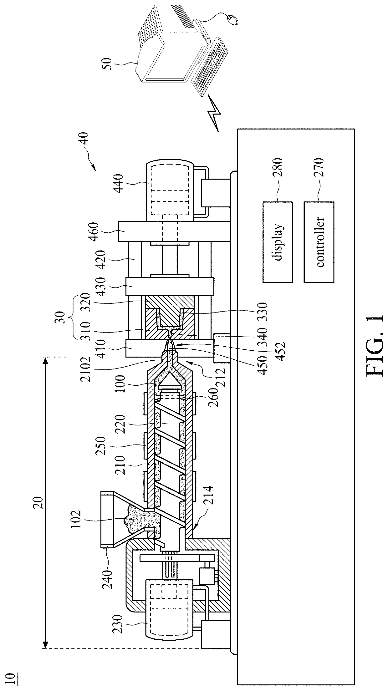
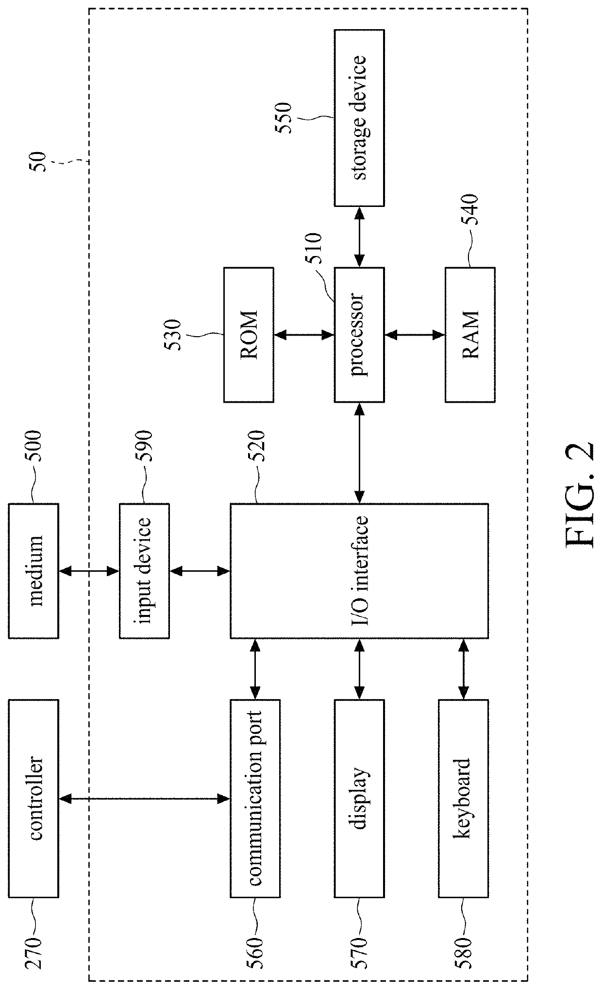
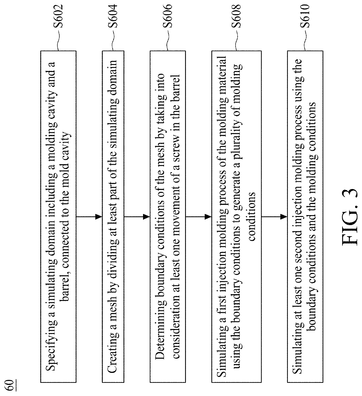
The present patent provides a computer-implemented simulation method for a molding process using a computer process. The method involves creating a simulating domain, dividing it into a mold cavity and a barrel of an injection machine, and determining boundary conditions based on the motion of a screw in the barrel to process the molding material. The method also includes simulating at least one injection-molding process of the molding material using the boundary conditions and the determined boundary conditions. The method further includes calculating the melt front of the molding material and simulating at least one second injection-molding process of the molding material. The boundary conditions are determined using a set of lines to divide the screw movement zone in the barrel into a set of layers. The density and viscosity of the element partially occupied by the screw and partially filled with the molding material are described by an equation. The amount of molding material injected into the mold cavity by the screw in the barrel is described by an equation. The foregoing has outlined the technical effects of the patent text.

Problems solved by technology

In general, the setting of molding conditions in an injection-molding machine requires a large number of trial molding operations and a lengthy setup time.
In other words, the molding conditions of the optimal injection-molded product are implemented by repetitive trial and error, which requires much time and labor.

Method used


Image

  • Computer-implemented simulation method for injection-molding process
  • Computer-implemented simulation method for injection-molding process
  • Computer-implemented simulation method for injection-molding process

Examples


Embodiment Construction

[0036]Embodiments, or examples, of the disclosure illustrated in the drawings are now described using specific language. It shall be understood that no limitation of the scope of the disclosure is hereby intended. Any alteration or modification of the described embodiments, and any further applications of principles described in this document, are to be considered as normally occurring to one of ordinary skill in the art to which the disclosure relates. Reference numerals may be repeated throughout the embodiments, but this does not necessarily mean that feature(s) of one embodiment apply to another embodiment, even if they share the same reference numeral.

[0037]It shall be understood that, although the terms first, second, third, etc. may be used herein to describe various elements, components, regions, layers or sections, these elements, components, regions, layers or sections are not limited by these terms. Rather, these terms are merely used to distinguish one element, component...


PUM

PropertyMeasurementUnit
Timeaaaaaaaaaa
Mesh sizeaaaaaaaaaa
Temperatureaaaaaaaaaa

Abstract

A computer-implemented simulation method for use in a molding process by a computer process is disclosed. The method includes steps of specifying a simulating domain comprising a mold cavity and a barrel of an injection machine, wherein the barrel is configured to connect to the mold cavity; creating at least one mesh by dividing at least part of the simulating domain; specifying boundary conditions of the mesh by taking into consideration at least one motion of a screw in the barrel; and simulating a first injection-molding process of a molding material by using the boundary conditions to generate a plurality of molding conditions.

Description

PRIORITY CLAIM AND CROSS-REFERENCE[0001]This application claims the priority benefit of U.S. provisional application Ser. No. 62 / 854,800, filed on May 30, 2019. The entirety of the above-mentioned patent application is hereby incorporated by reference herein and made a part of this specification.TECHNICAL FIELD[0002]The present disclosure relates to a computer-implemented simulation method for an injection-molding process.DISCUSSION OF THE BACKGROUND[0003]Injection molding is an important industrial process for producing large quantities of complex plastic parts. New polymers and the demand for high-quality electronics, consumer products, automobiles and aircraft have forced engineers and designs to improve mold-tooling efficiency and the quality of final parts.[0004]In general, the setting of molding conditions in an injection-molding machine requires a large number of trial molding operations and a lengthy setup time. The analytical data generated by a virtual molding process usin...

Claims


Application Information

Patent Timeline
IPC IPC(8): B29C45/76B29C45/80B29C45/77B29C45/78G06F30/23G06F113/22
CPCB29C45/7693B29C45/7646B29C45/77B29C45/78B29C45/80G06F30/23B29C2945/76498B29C2945/76531B29C2945/76538B29C2945/76545B29C2945/76595B29C2945/76612B29C2945/76665G06F2113/22B29C45/766B29C2945/7601B29C2945/7606B29C2945/76274B29C2945/76287B29C2945/76765B29C2945/76859
Inventor HSU, CHIH-CHUNGZHOU, YOU-SHENGHSU, CHIA-HSIANGCHANG, RONG-YEU
Owner CORETECH SYST
Learn More