Jig

a technology of jig and probe head, applied in the field of jig, can solve the problems of bending, breakage, affecting the accuracy of the measurement,

Active Publication Date: 2021-03-30
NIHON MICRONICS
View PDF15 Cites 1 Cited by
  • Summary
  • Abstract
  • Description
  • Claims
  • Application Information

AI Technical Summary

Benefits of technology

[0008]The plate can include a plurality of holes respectively corresponding to the plurality of set screws. Accordingly, after the jig is attached to the probe head, the tip end portion of a screwdriver can be inserted into each of the holes of the plate corresponding to the set screws to loosen and pull out each of the set screws via the holes corresponding to the set screws, and securement of the probe head to the wiring substrate can thus be released. The magnet may be a permanent magnet or an electromagnet. The probe includes a barrel including a spring portion that can expand and contract in an axial direction thereof and a plunger including a main body arranged in the barrel and secured to the barrel and a tip end portion protruded out of the barrel, for example. The barrel defines the upper end portion and the intermediate portion of each of the probes, and the tip end portion of the plunger defines the lower end portion of each of the probes.

Problems solved by technology

Meanwhile, each probe of the probe head is subject to abrasion, bending, breakage, a conduction failure, and the like due to usage thereof, and the probe head is detached from the electric connecting apparatus for replacement of the probe.

Method used


Image

  • Jig
  • Jig
  • Jig

Examples


Embodiment Construction

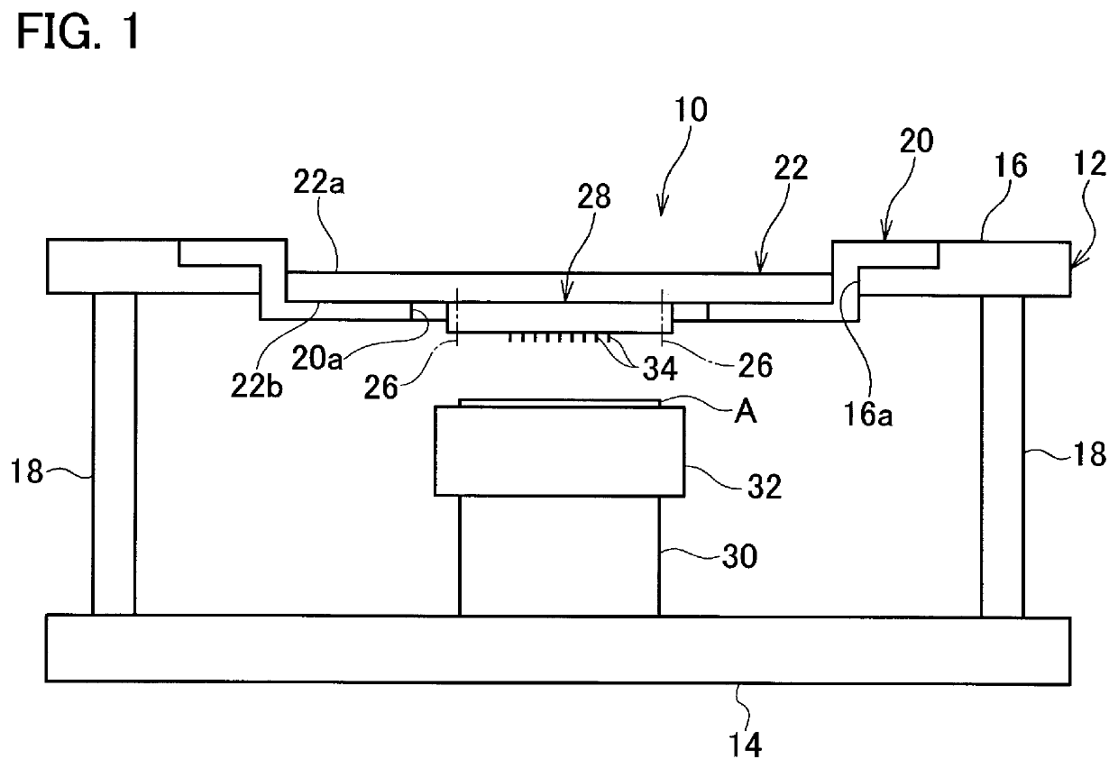
[0015]Referring to FIG. 1, an electric connecting apparatus to which a jig 50 (refer to FIG. 4 described below) according to the present invention is applied is entirely illustrated with reference sign 10. The electric connecting apparatus 10 functions to electrically connect a device under test A such as a wafer, a printed wiring board etc. to a testing apparatus (not illustrated) performing a test to check an electric characteristic, a conductive state etc. of the device under test A, for example. The test of the device under test A is performed by supplying electric current or an electric signal from the testing apparatus via the electric connecting apparatus 10 to the device under test A and detecting feedback electric current or a feedback electric signal returning from the device under test A via the electric connecting apparatus 10 to the testing apparatus.

[0016]The device under test A is arranged in a support frame 12 prepared to support the electric connecting apparatus 10....


PUM


Abstract

Provided is a jig enabling detachment and attachment of a probe head from and to an electric connecting apparatus without using a special holding device. A jig (50) is applied to an electric connecting apparatus (10) electrically connecting a device under test to a testing apparatus for the device under test. The electric connecting apparatus includes a wiring substrate (22) and a probe head (28) secured to the wiring substrate with a plurality of set screws (26) and including a plurality of probes (34) made of a magnetic body. The jig (50) includes a plate (52) and a magnet (54) attached to the plate. The plate can detachably be attached to the probe head, and the magnet is opposed to a lower end portion (34b) of each of the probes.

Description

TECHNICAL FIELD[0001]The present invention relates to a jig to be applied to an electric connecting apparatus.BACKGROUND ART[0002]An electric connecting apparatus to which the present invention is applied includes a wiring substrate and a probe head attached to the wiring substrate. A probe head used for a vertical probe card includes a plurality of probes each including upper and lower end portions and an intermediate portion between the upper and lower end portions and made of a magnetic body and a support body supporting the probes. The support body includes an upper plate and a lower plate which are parallel to each other, the upper plate includes holes allowing the lower end portions, the intermediate portions, and the upper end portions of the respective probes to pass therethrough, and the lower plate includes holes allowing the lower end portions of the respective probes to pass therethrough and preventing the intermediate portions of the respective probes from passing there...

Claims


Application Information

Patent Timeline
Patent Type & Authority Patents(United States)
IPC IPC(8): G01R1/07G01R1/073G01R1/067G01R1/16G01R31/28
CPCG01R1/073G01R1/06722G01R1/16G01R31/2808G01R31/2863G01R1/0408G01R1/06G01R1/067G01R31/2865G01R31/2886
Inventor SHUTO, AKIHIRO
Owner NIHON MICRONICS
Why Eureka
Try Eureka