
Display device

a display device and display technology, applied in the field of display devices, can solve the problems of affecting the appearance quality of products, affecting the quality of products, and certain gaps still required, and achieve the effect of reducing the opportunity

Active Publication Date: 2021-03-30
AU OPTRONICS CORP
View PDF20 Cites 0 Cited by
  • Summary
  • Abstract
  • Description
  • Claims
  • Application Information

AI Technical Summary

Benefits of technology

The patent text describes a display device that has various technical effects. Firstly, it reduces the possibility of users seeing elements in the display device. Secondly, it improves the overall visual appearance of the display device. Thirdly, it provides better support to a portion of a film that protrudes out of the display panels. The technical effects of the patent are achieved through a specific arrangement of a flexible connecting unit and two different glues. The first glue is used to provide support to the outer surface of the film, while the second glue is used to provide a cushion to decrease the risk of the flexible connecting unit collapsing.

Problems solved by technology

However, at the same time, thinner outer frames can't cover the outer surface of the display panel, as a result, users can easily be aware of the interface between the outer frame and the display panel.
However due to the need to take into accounts an allowed difference in assembly and the fact that the outer frame might be subject to external force and press upon the display panel, a certain gap is still required to be keep a distance between the outer filter and the edge of the display panel.
But because of existence of the gap, users may see the elements or circuits within the display device through the gap, affecting the quality of product appearance.
In addition, the light in the display device may also pass through this gap and leak out to produce a light leak.

Method used


Image

  • Display device
  • Display device
  • Display device

Examples


Embodiment Construction

[0016]The connecting elements according to the present invention will be described in detail below through embodiments and with reference to the accompanying drawings, a person having ordinary skill in the art may understand the advantages and effects of the present disclosure through the contents disclosed in the present specification. However, the contents shown in the following sentences never limit the scope of the present disclosure. Without departing from the conception principles of the present invention, a person having ordinary skill in the present art may realize the present disclosure through other embodiments based on different views and applications. In the attached FIGs, for the purpose of clarification, the thicknesses of layers, films, panels, regions and the like are amplified. In the whole specification, the same marks represent the same element. It should be understood that, when an element such as a layer, a film, a panel, a region or a substrate are described as...


PUM

PropertyMeasurementUnit
widthaaaaaaaaaa
Shore hardnessaaaaaaaaaa

Abstract

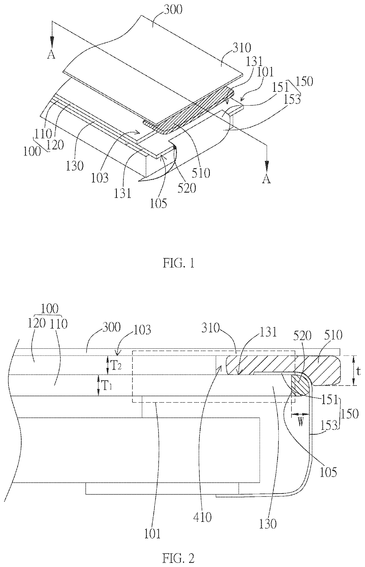
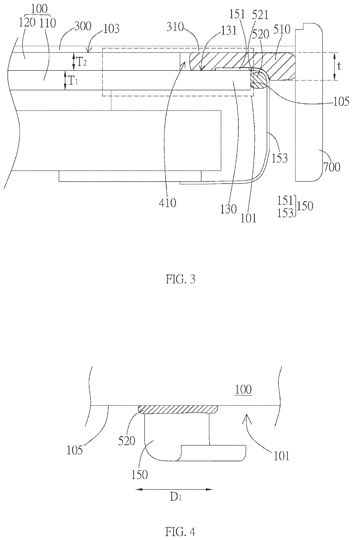
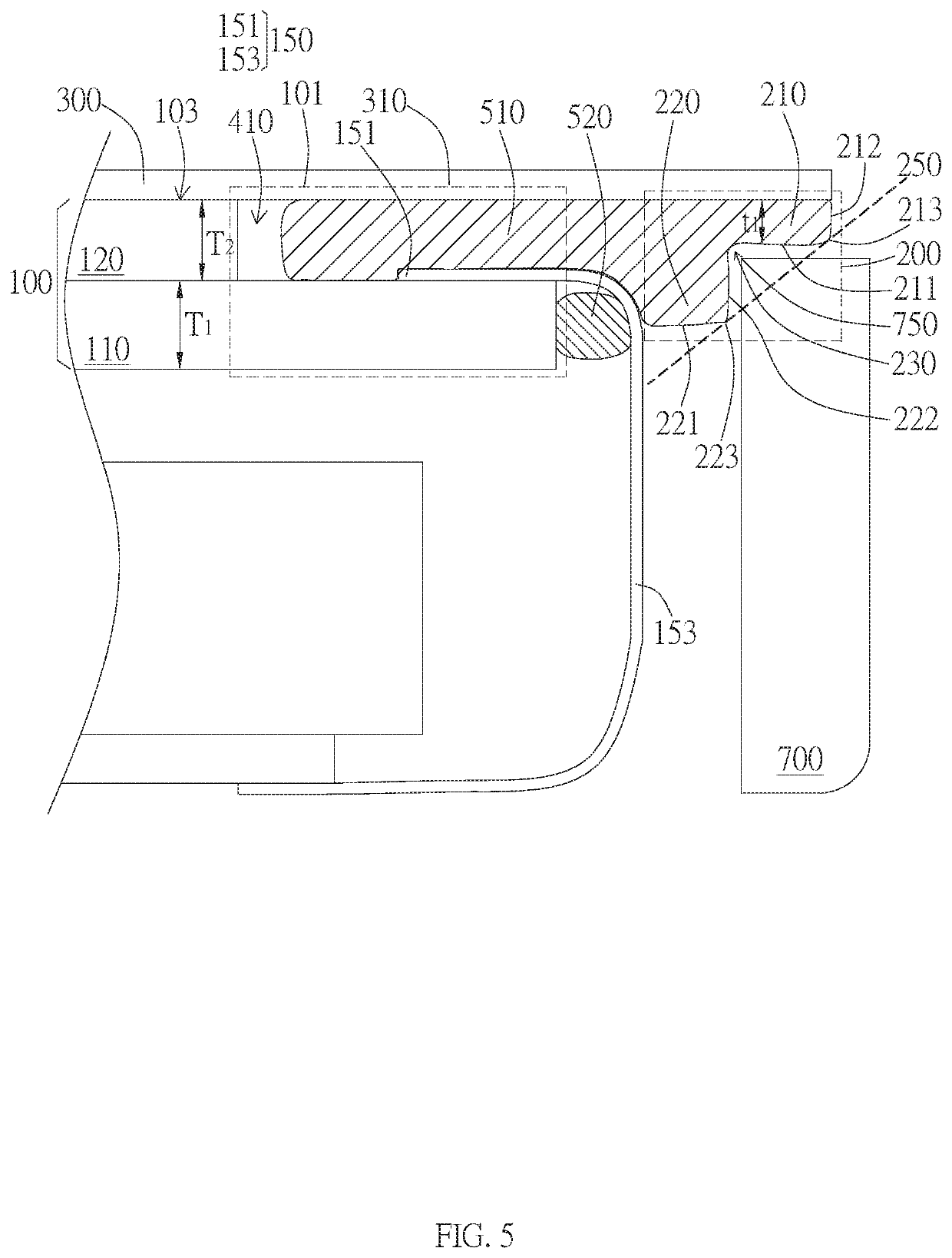
A display device including a display panel, a film, a flexible connecting unit, a first glue, and a second glue. The film is stacked on an outer surface of the display panel and has an extension portion extending out of the outer surface. The flexible connecting unit connects to the display panel and extends out from a first end of the display panel. A gap exists between the flexible connecting unit and the extension portion while the first glue is at least partially distributed within the gap. The second glue at least partially distributed between the flexible connecting unit and the edge of the first end, and the second glue is different from the first glue.

Description

BACKGROUND OF THE INVENTION1. Field of the Invention[0001]The present disclosure relates to a display device, in particular, to a display device having a film extending out of a display panel on the display panel.2. Description of the Prior Art[0002]In recent years, various types of display devices are already broadly used in our daily living. Things like televisions, personal computers, mobile phones, video games, and devices for cars all need to use display devices. In respect to technological development of display devices, there is a continual trend towards larger displays and the narrower frames, or even no frame, in an effort to give people a better visual experience.[0003]In the pursuit of display devices with narrower frames or no frame, traditional designs continue to decrease the thickness of the outer frame of the device to achieve better visual effects. However, at the same time, thinner outer frames can't cover the outer surface of the display panel, as a result, users ...

Claims


Application Information

Patent Timeline
Patent Type & Authority Patents(United States)
IPC IPC(8): G02F1/1333G02F1/1345
CPCG02F1/1345G02F1/133308G02F2202/28G09F9/30G02F1/13452
Inventor CHIEN, CHIH-WEITSENG, LI-WEITSAI, SHAU-YU
Owner AU OPTRONICS CORP
Learn More