Headrest moving device
a moving device and headrest technology, applied in the direction of chairs, vehicle components, vehicle arrangements, etc., can solve the problems of increased weight, increased manufacturing cost, complex manufacturing process, etc., and achieve the effect of reducing the number of components and the weight of the apparatus, reducing manufacturing cost, and simplifying the structure of the apparatus
- Summary
- Abstract
- Description
- Claims
- Application Information
AI Technical Summary
Benefits of technology
Problems solved by technology
Method used
Image
Examples
embodiment 1
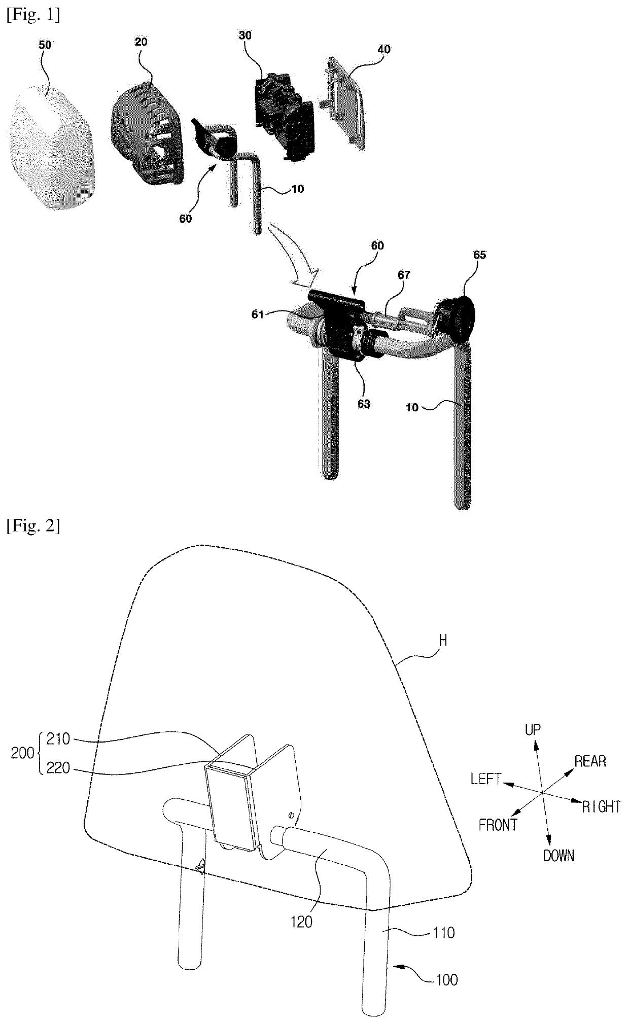
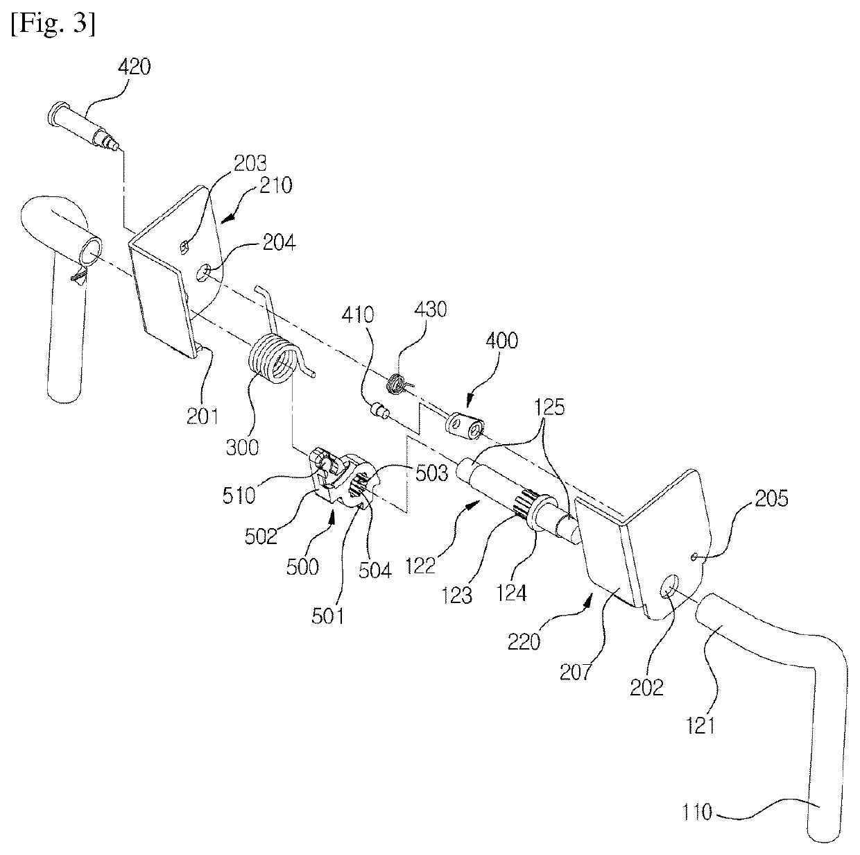
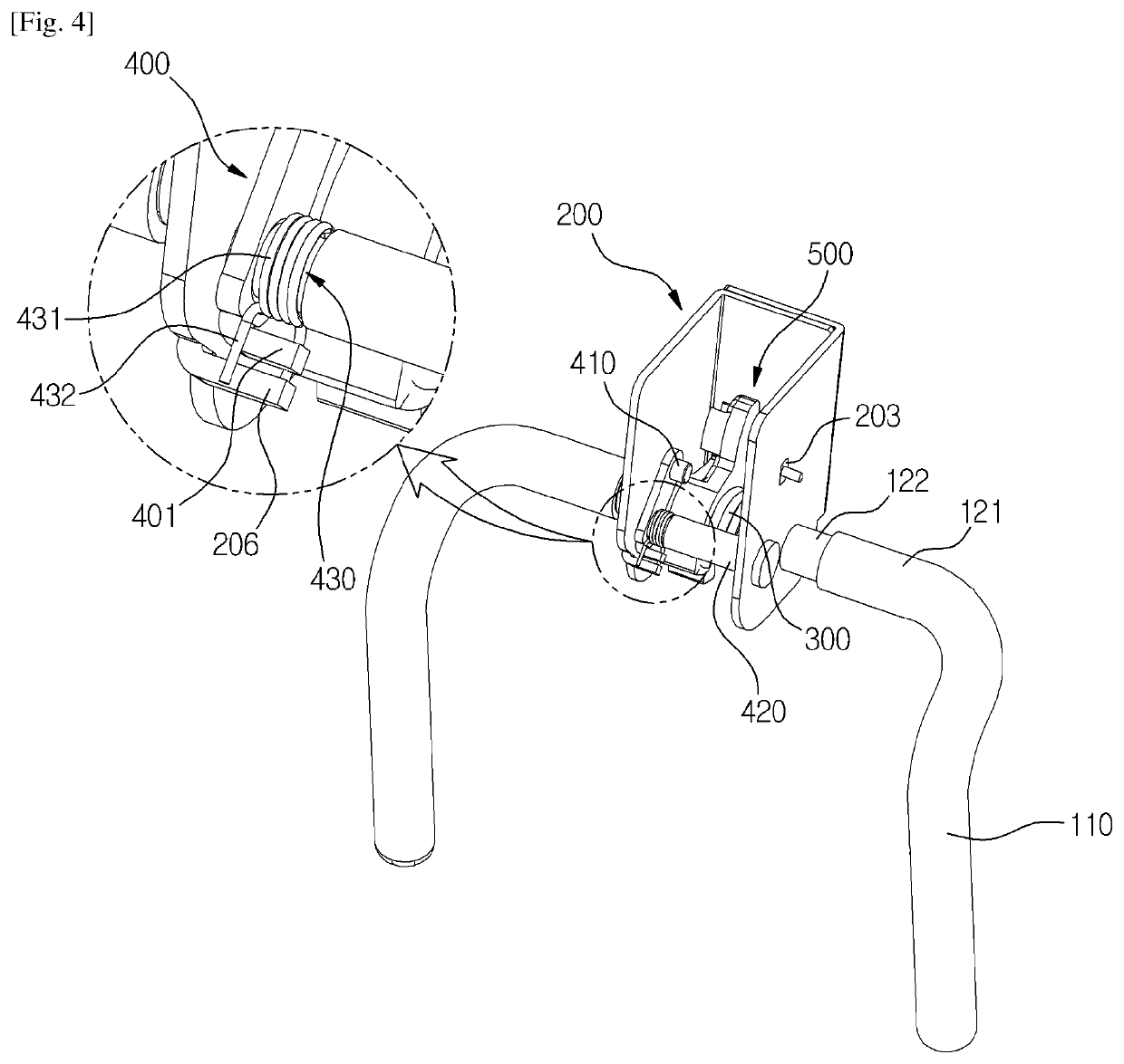
[0049]As illustrated in FIGS. 2 to 8, a headrest moving device of the present exemplary embodiments is characterized in that and comprises: a first member 100; a second member 200 capable of rotating or sliding with respect to the first member 100; a return spring 300 for returning the second member 200 with respect to the first member 100; a moving member 400 rotatably connected to the second member 200; and a guide member 500 connected to the first member 100 for guiding the moving member 400 and formed with a locking groove 513 wherein the moving member 400 is stopped.
[0050]In the present exemplary embodiment, the first member 100 is a stay rod, and the second member 200 is a bracket. Unlike to this, the first member may be a bracket and the second member may be a stay rod.
[0051]The first member 100 is fixed along the front-to-rear direction with respect to the seat, and not being moved with respect to the seat. That is, the first member 100 is connected to the seat.
[0052]The sec...
embodiment 2
[0142]In describing the headrest moving device according to the second exemplary embodiment of the present invention, same symbols will be used for the same or similar elements as those of the headrest moving device according to the previous exemplary embodiment of the present invention, and the detailed description and illustration will be omitted.
[0143]As illustrated in FIGS. 9 and 10, the headrest moving device according to the second exemplary embodiment is locked as a moving member 400 is inserted into a locking groove 513 of a guide member 500′ when the headrest is in an upright state, and the guide member 500′ is installed in a first member 100 in a way that the moving member 400 is separated from the locking groove 513 when the headrest is in a folded state.
[0144]The elastic force of the return spring is applied clockwise to a second member 200 wherein the moving member 400 is rotatably mounted.
[0145]A first portion 501′ in which a first stopping portion 201 is stopped is di...
embodiment 3
[0151]In describing the headrest moving device according to the third exemplary embodiment of the present invention, same symbols will be used for the same or similar elements as those of the headrest moving device according to the previous exemplary embodiments of the present invention, and the detailed description and illustration will be omitted.
[0152]As illustrated in FIGS. 12 to 14, a first member 100′ of the headrest moving device according to the third exemplary embodiment of the present invention is connected to the headrest, and a second member 200′ is connected to the seat.
[0153]The headrest is provided on the upper side of a vertical portion 110 of the first member 100′. A horizontal portion 120 is disposed at the lower side of the vertical portion 110. A guide member 500″ is provided on the horizontal portion 120. A first portion 501″ of the guide member 500″ is disposed at the rear upper of the second portion 502″. A guide pathway formed in the guide member 500″ at the ...
PUM
 Abstract
Description
Claims
Application Information
 - R&D
- Intellectual Property
- Life Sciences
- Materials
- Tech Scout
- Unparalleled Data Quality
- Higher Quality Content
- 60% Fewer Hallucinations
Browse by: Latest US Patents, China's latest patents, Technical Efficacy Thesaurus, Application Domain, Technology Topic, Popular Technical Reports.
© 2025 PatSnap. All rights reserved.Legal|Privacy policy|Modern Slavery Act Transparency Statement|Sitemap|About US| Contact US: help@patsnap.com


