
Method for measuring amount of applied coating

a technology of applied coating and measurement value, which is applied in the direction of measurement devices, instruments, and using wave/particle radiation means, etc., can solve the problems of large error in the amount of applied coating calculated from measurement values obtained at different points before and after coating application, and the actual amount of applied coating is large error in the actual amount of applied coating, etc., to achieve accurate calculation of applied coating amount and accurate measurement of applied coating amount

Active Publication Date: 2021-04-20
HONDA MOTOR CO LTD
View PDF5 Cites 0 Cited by
  • Summary
  • Abstract
  • Description
  • Claims
  • Application Information

AI Technical Summary

Benefits of technology

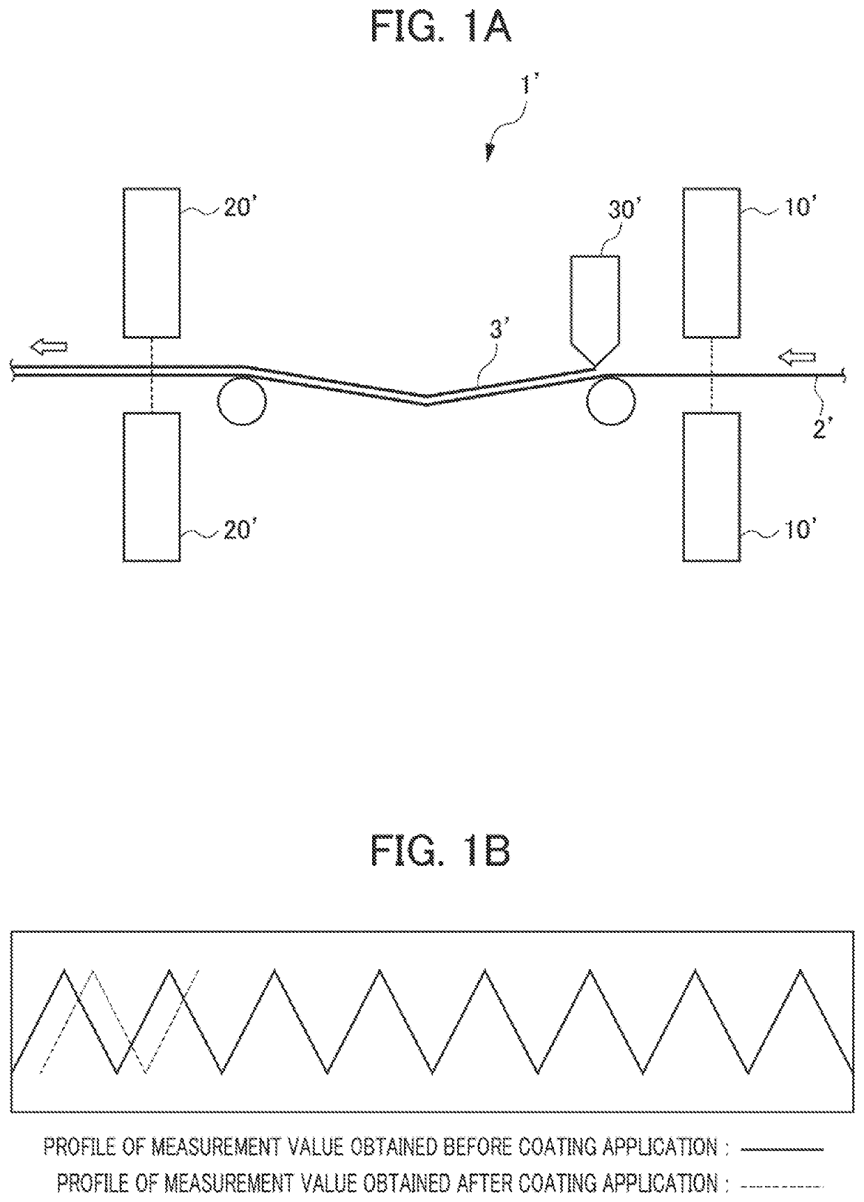
[0007]The present disclosure has been made in view of the foregoing background, and it is an object of the present disclosure to provide a method for measuring an amount of an applied coating, the method being capable of accurately measuring the amount of the applied coating even if a deviation occurs between measurement points during conveyance.
[0009]According to the method of the first aspect, even if a measurement point of the second measurement information is deviated in a conveyance direction from a measurement point of the first measurement information, the deviation of the second measurement information in the conveyance direction is corrected through the matching of the shape of the first profile of irregularities and the shape of the second profile of irregularities. This feature makes it possible to measure the amount of the applied coating with accuracy.
[0011]According to the method of the second aspect, a deviation in the conveyance direction can be corrected using the profiles in the conveyance direction. This feature makes it possible to set a measurement range of the sensors to be small in a width direction.
[0013]According to the method of the third aspect, a deviation in the conveyance direction is corrected using the profiles in the direction orthogonal to the conveyance direction. Therefore, at the same time as the acquisition of the second measurement information, a second profile of irregularities that corresponds to the acquired second measurement information can be generated. This feature makes it possible to accurately calculate the amount of the applied coating through the matching of the profiles of irregularities before and after the coating application, substantially at the same time as the acquisition of the second measurement information.
[0014]The present disclosure provides a method for measuring an amount of an applied coating, the method being capable of accurately measuring the amount of the applied coating even if a deviation occurs between measurement points during conveyance.

Problems solved by technology

Consequently, the amount of the applied coating is calculated from the difference between a measurement value obtained at a measurement point before the coating application and a measurement value obtained at a different measurement point after the coating application, resulting in an error with respect to the actual amount of the applied coating.
In particular, in the case where the substrate sheet is, for example, carbon paper for fuel cells, the in-plane mass of the substrate is distributed irregularly and unevenly.
Therefore, an amount of an applied coating calculated from the measurement values obtained at different points before and after the coating application contains a large error with respect to the actual amount of the applied coating.

Method used


Image

  • Method for measuring amount of applied coating
  • Method for measuring amount of applied coating
  • Method for measuring amount of applied coating

Examples


first embodiment

[0024]the present disclosure will be described below with reference to the drawings. Note that the present disclosure is not limited to the following embodiments.

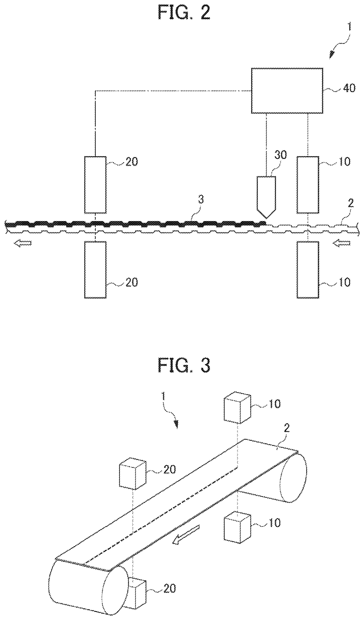
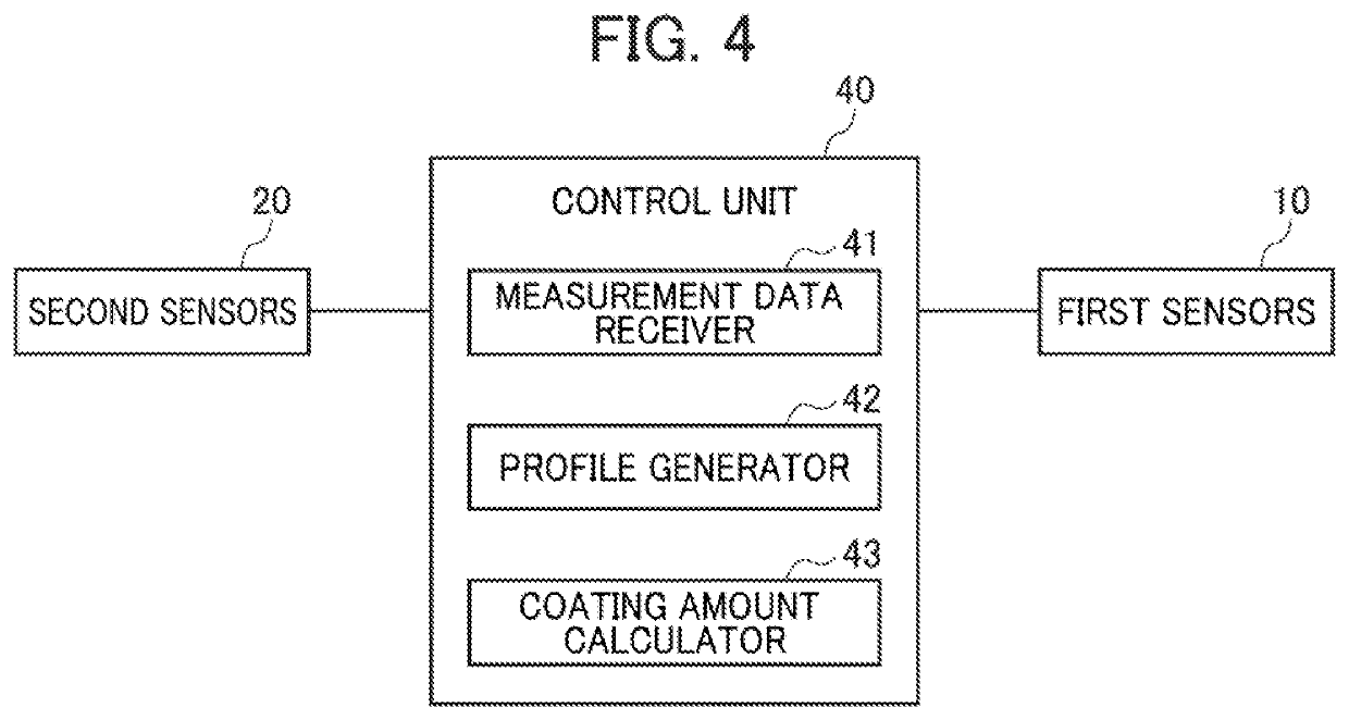
[0025]First, a coating apparatus 1 and a substrate sheet 2 according to the first embodiment will be described with reference to FIGS. 2 and 3. FIG. 2 is a front view of the coating apparatus 1 and the substrate sheet 2. FIG. 3 is a perspective view showing a measurement range on the substrate sheet 2, the measurement range being covered by first sensors 10 and second sensors 20 of the coating apparatus 1. In FIG. 3, a coating machine 30 and a control unit 40 are not shown. FIG. 4 is a block diagram showing configurations for the first sensors 10, the second sensors 20, and the control unit 40.

[0026]The substrate sheet 2 is an elongated sheet of carbon paper. The substrate sheet 2 is conveyed in the coating apparatus 1 from right to left in FIGS. 2 and 3. Carbon paper has in-plane mass distributed irregularly and unevenly, ...

second embodiment

[0046]FIG. 6 is a perspective view of the present disclosure, and shows a substrate sheet 2A and a measurement range on the substrate sheet 2A covered by first sensors 10A and second sensors 20A of the coating apparatus 1A. Like the coating apparatus 1, the coating apparatus 1A includes the first sensors 10A, the second sensors 20A, a coating machine 30 (not shown), and a control unit 40 (not shown). In FIG. 6, the coating machine 30 and the control unit 40 are not shown so that the measurement range on the substrate sheet 2A covered by the first sensors 10A and the second sensors 20A can be viewed.

[0047]As shown in FIG. 6, the first sensors 10A and the second sensors 20A of the coating apparatus 1A move in the width direction of the substrate sheet 2A. Specifically, the first sensors 10A and the second sensors 20A are installed to move in synchronization with each other and to be able to measure the same points on the substrate sheet 2A. In addition, the distance from the first sen...

third embodiment

[0063]In the method for measuring the amount of the applied coating described above, the first and second profiles of irregularities are of the measurement range set only in the width direction of the substrate sheet 2B. However, the profiles of irregularities may be three-dimensional profiles including a profile of a measurement range in the conveyance direction. In this case, since the three-dimensional first profile and second profile of irregularities are matched to each other, a deviation of the second measurement information in the conveyance direction can be corrected with higher accuracy.

[0064]Note that the present disclosure is not limited to the above-described embodiments, and encompasses variations, improvements, and the like within a range in which the object of the present disclosure is achieved.

[0065]In the above-described embodiment, the first measurement information and the second measurement information indicating the shape of the irregularities of the substrate s...


PUM


Abstract

The method includes: a first profile generation step of generating a first profile of irregularities in a measurement range set on the substrate sheet (2), based on first measurement information acquired at a location upstream of the coating machine (30) and indicating a shape of irregularities of the substrate sheet (2); a second profile generation step of generating a second profile of irregularities in the measurement range, based on second measurement information acquired at a location downstream of the coating machine (30) and indicating the shape of the irregularities of the substrate sheet (2); and a coating amount calculation step of calculating the amount of the applied coating from a difference between the first measurement information and the second measurement information, based on a positional relationship in which the shape of the first profile of irregularities and the shape of the second profile of irregularities are matched to each other.

Description

BACKGROUND OF THE INVENTIONField of the Invention[0001]The present disclosure relates to a method for measuring an amount of an applied coating.Related Art[0002]A method has conventionally been used in which an amount of a coating applied to a substrate sheet such as carbon paper for fuel cells is measured while the substrate sheet is being conveyed. For example, Patent Document 1 discloses a method for evaluating the density of a coating material and the uniformity of an amount of the coating material to be applied, immediately before the coating material is applied to a web.[0003]Patent Document 1: Japanese Unexamined Patent Application, Publication No. 2010-205679SUMMARY OF THE INVENTION[0004]Meanwhile, there is a measurement method in which an amount of an applied coating is calculated using sensors that measure the thickness, the mass, or the like of a substrate sheet before and after the application of the coating. Specifically, the sensors are respectively arranged upstream a...

Claims


Application Information

Patent Timeline
Patent Type & Authority Patents(United States)
IPC IPC(8): G01B21/08
CPCG01B21/08G01B11/0616G01B11/24G01B15/02G01B15/04G01B21/20G01G17/00G01B15/025G01B15/045
Inventor KURATA, HIROSHIKONISHI, SHUNSUKE
Owner HONDA MOTOR CO LTD
Learn More