Wireless power transmission device and method

a technology of wireless power transmission and wired power, which is applied in the direction of instruments, lenses, transportation and packaging, etc., can solve the problems of difficult realistically matching, difficult to achieve, and the maturity of the technology has not been fully reached, so as to prevent the efficiency of a wireless power system from being degraded, and improve the efficiency of wireless power transmission

Active Publication Date: 2021-04-27
LG ELECTRONICS INC
View PDF17 Cites 0 Cited by
  • Summary
  • Abstract
  • Description
  • Claims
  • Application Information

AI Technical Summary

Benefits of technology

[0017]According to at least one embodiment of the present disclosure, wireless power transmission efficiency can be improved based on an effective light receiving area of a wireless power receiving side.
[0018]According to at least one embodiment of the present disclosure, it is possible to prevent the wireless power transmission efficiency from being degraded by changing a transmission mechanism adaptive to a change in the effective light receiving area of the wireless power receiving side.
[0019]According to at least one embodiment of the present disclosure, it is possible to prevent the efficiency of a wireless power system from being degraded and / or improve the efficiency of the wireless power system even though there are various events during a wireless power transmission process.
[0020]It will be appreciated by persons skilled in the art that the effects that can be achieved through the present invention are not limited to what has been particularly described hereinabove and other advantages of the present invention will be more clearly understood from the following detailed description.

Problems solved by technology

On the other hand, the long-range wireless power transmission technology has been researched for an unmanned aerial vehicle with a special purpose such as a military drone, but the maturity of the technology has not been fully reached.
Meanwhile, wireless power transmission may have a problem of performance degradation due to a mismatch in alignment between transmitting and receiving sides.
Although this problem can be solved by adjusting the alignment between the transmitting and receiving sides, it is difficult to realistically match the alignment between the transmitting and receiving sides, and thus the problem that the efficiency of the wireless power transmission is degraded still exists.

Method used


Image

  • Wireless power transmission device and method
  • Wireless power transmission device and method
  • Wireless power transmission device and method

Examples


Embodiment Construction

[0030]Description will now be given in detail according to exemplary embodiments disclosed herein, with reference to the accompanying drawings. For the sake of brief description with reference to the drawings, the same or equivalent components may be provided with the same reference numbers, and description thereof will not be repeated.

[0031]In general, a suffix such as “module” and “unit” may be used to refer to elements or components. Use of such a suffix herein is merely intended to facilitate description of the specification, and the suffix itself is not intended to give any special meaning or function.

[0032]It will be understood that although the terms first, second, etc. may be used herein to describe various elements, these elements should not be limited by these terms. These terms are generally only used to distinguish one element from another.

[0033]It will be understood that when an element is referred to as being “connected with” another element, the element can be directl...


PUM


Abstract

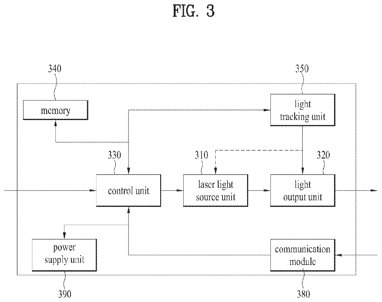
The present specification discloses a wireless power transmission device and method thereof. Here, the wireless power transmission device according to an embodiment of the present invention includes: a laser light source unit; a light output unit which emits laser light generated from the laser light source to a light receiving unit of the wireless power receiving device; and a control unit which controls shaping of the emitted light according to the angle of arrival with the light receiving unit so that an overfill loss is less than a predetermined threshold value. Here, the control unit detects the point at which the power conversion efficiency of the light receiving unit is highest, and sets and controls the power density value of the emitted light at the detected point.

Description

CROSS-REFERENCE TO RELATED APPLICATIONS[0001]This application is the National Stage filing under 35 U.S.C. 371 of International Application No. PCT / KR2017 / 008388, filed on Aug. 3, 2017, which claims the benefit of earlier filing date and right of priority to Korean Application No. 10-2016-0168589, filed on Dec. 12, 2016, the contents of which are all hereby incorporated by reference herein in their entirety.TECHNICAL FIELD[0002]The present disclosure relates to a wireless power transmission apparatus and method thereof.BACKGROUND ART[0003]In recent years, wireless power transmission technology (technique) has been widely deployed. For example, the wireless power transmission technology has been researched and developed not only for wireless charging of a smartphone, an electric vehicle, etc. but also for application fields such as provision of power to a wearable device, a sensor for Internet of Things (IoT), etc.[0004]The wireless power transmission technology is technology for tra...

Claims


Application Information

Patent Timeline
Patent Type & Authority Patents(United States)
IPC IPC(8): H02J50/30H02J50/80G02B3/00H02J7/02
CPCH02J50/30G02B3/0037H02J7/025H02J50/80G02B2003/0093G02B19/0014G02B19/0047G02B26/101G02B27/0911H01S3/00H01S3/0057H04B10/807H02J50/005
Inventor KIM, KYUNGHWANYOUN, JINHOLEE, SEONGHUN
Owner LG ELECTRONICS INC
Why Eureka
Try Eureka