Injector arrangement for diesel engines using slurry or emulsion fuels

a diesel type and injector technology, applied in the direction of machines/engines, combustion types, lighting and heating apparatus, etc., can solve the problems of increasing the volume of fuel occupying the pump, and achieve the effect of reducing or eliminating residual diesel fuel, facilitating fast and thorough fuel flushing, and reducing viscosity

Active Publication Date: 2021-05-04
COMMONWEALTH SCI & IND RES ORG
View PDF12 Cites 0 Cited by
  • Summary
  • Abstract
  • Description
  • Claims
  • Application Information

AI Technical Summary

Benefits of technology

[0013]The present invention advantageously exposes the check valve outlet region to the pressurised fuel flow in the injection path between the pumping element and the injector nozzle and, in this manner, reduces or eliminates the formation of undesirable sludge in the vicinity of the check valve outlet. The fuel inlet check valves of previous carbonaceous slurry engines are conventionally isolated from fuel flow between the pump and the nozzle (for example, communicating with the injection path via a narrow passageway or conduit). The present invention achieves a significant improvement upon this configuration by arranging the check valve such that the outlet region is regularly flushed by pressurised flow travelling along the injection path. In this manner, the present invention can reduce or eliminate undesirable ‘dead zones’ or areas of recirculation in the vicinity of the check valve outlet and immediately downstream therefrom. Exposure of the outlet region to said fuel flow advantageously minimises or eliminates a potentially stagnant volume of fuel immediately downstream of the check valve which is, instead, flushed in highly regular intervals by fuel flow along the injection path. The present invention also eliminates the need for a narrow duct or conduit connecting the check valve to the injection path which, in previous systems, the Applicant has discovered to be at risk of blockage due to sludge formation.
[0040]The avoidance of fuel segregation can, for example, involve maintaining a substantially homogenous carbonaceous slurry fuel. That is, avoiding segregation of the carbonaceous particulate from the liquid portion of the slurry fuel which can cause carbonaceous particles to settle and form sludge. In some instances, this can be achieved by maintaining a sufficient rate of shear throughout the fuel system. This outcome can also be achieved or can be facilitated by reducing or eliminating stagnant fuel zones in the outlet region.

Problems solved by technology

In this arrangement, downward movement of the plunger reduces the volume of the pump chamber causing an increase in pressure within the volume of fuel occupying the pump chamber and the fuel duct.

Method used


Image

  • Injector arrangement for diesel engines using slurry or emulsion fuels
  • Injector arrangement for diesel engines using slurry or emulsion fuels
  • Injector arrangement for diesel engines using slurry or emulsion fuels

Examples


first embodiment

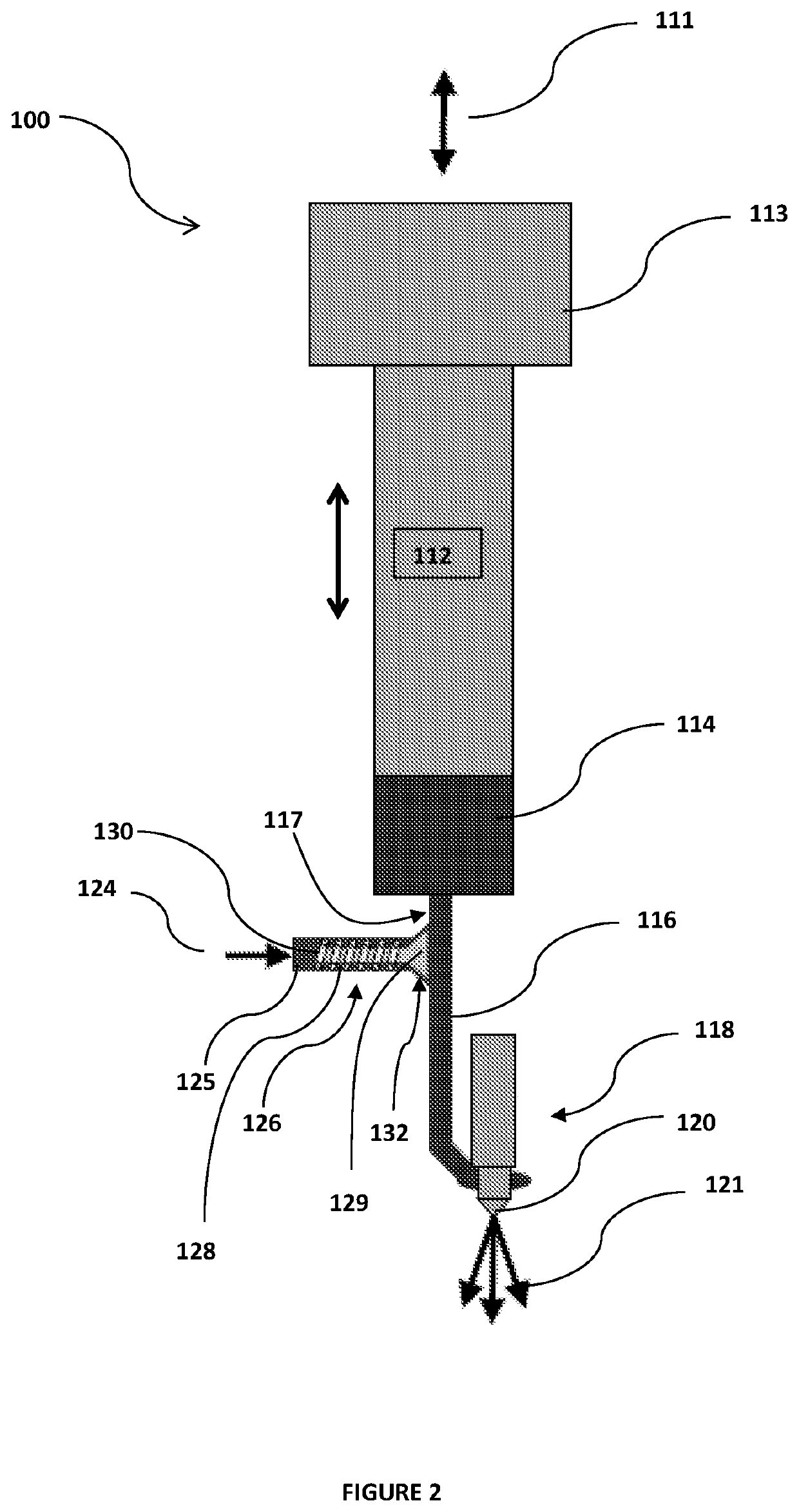
[0067]Turning now to FIG. 2, there is illustrated a fuel injection arrangement 100 according to the present invention. Arrangement 100 includes an injector nozzle 120 for injecting a fuel spray 121 into a combustion chamber (not shown). Injector nozzle 120 is part of a larger injector nozzle assembly 118 which includes an internal spring-loaded and normally closed nozzle valve (not shown) configured to open when pressure in the upstream fuel line increases to a predetermined valve opening pressure. Upon opening of the normally closed nozzle valve, fuel spray 121 is injected into the combustion chamber until the subsequent reduction in upstream fuel line pressure reduces below the nozzle valve opening pressure whereupon the nozzle valve returns to its normally closed position and fuel spray 121 into the combustion chamber is terminated until the next injection event.

[0068]The fuel line immediately upstream of the injector nozzle assembly 118 comprises a fuel duct 116 communicating be...

second embodiment

[0073]FIG. 3 illustrates the present invention comprising fuel injection arrangement 200 which provides a variation on the arrangement of check valve 126 illustrated and described above with respect to FIG. 2. Arrangement 200 includes a check valve 226 comprising a spring-loaded normally-closed poppet valve similar to the arrangement of check valve 126 in FIG. 2 except that valve stem 228 and helical spring 230 are locate outside of the fuel supply 224 which communicates with a small fuel chamber 236 located behind valve seat 232 and upstream of valve head 229. Valve stem 228 extends through an opening in the fuel inlet chamber 236. Seal oil 234 is applied to valve stem 228 within a stem housing (not shown) at higher pressure than the fuel within the fuel inlet chamber 236 to prevent fuel ingress from the inlet chamber 236 into the stem housing. This form of the invention advantageously isolates the valve stem 228 and valve spring 230 from the fuel supply 224 further reducing the po...

third embodiment

[0074]FIG. 4 illustrates a fuel injection arrangement 300 comprising the present invention. In contrast to the spring-loaded poppet valves of previous injection arrangements 100 and 200, arrangement 300 includes a check valve comprised of a floating ball check valve 326. In alternative embodiments of the present invention, check valve 326 could comprise alternative floating check valves such as a floating poppet valve. As illustrated in FIG. 4, ball check valve 326 includes a floating ball 329 normally seated in valve seat 332 and retained therein by the pressure differential between the injection path and the fuel inlet conduit 325. An extendable follower 338 is located adjacent to ball 329 limiting the range of movement of ball 329. In particular embodiments, the follower is spring-loaded to urge the ball toward the valve seat. A decrease in pressure within the injection path on the downstream side of check valve 326 causes floating ball 329 to unseat from valve seat 332 and there...


PUM


Abstract

The present invention relates to a fuel injection arrangement for a diesel type engine configured to use carbonaceous aqueous slurry fuels. The fuel injection arrangement includes an injector nozzle for injecting fuel into a combustion chamber; a pump chamber housing a fuel pumping element for generating a pressurised fuel flow to the injector nozzle along an injection path between the pumping element and the injector nozzle; and a check valve connected to a fuel supply for regulating and supplying fuel to the injection path via a check valve outlet. A region immediately downstream of the check valve outlet defines an outlet region and the check valve is arranged to expose the outlet region to the pressurised fuel flow to facilitate flushing of the outlet region during fuel flow between the pumping element and the injector nozzle.

Description

PRIORITY CROSS REFERENCE[0001]The present application is a U.S. National Phase Application under 35 U.S.C. § 371 of International Application No. PCT / AU2017 / 050918, filed on 29 Aug. 2017, which claims priority from Australian Provisional Patent Application No. 2016903419 filed 29 Aug. 2016 and Australian Provisional Patent Application No. 2016905343 filed 23 Dec. 2016, the contents of which are incorporated by reference into this specification.TECHNICAL FIELD[0002]The present invention generally relates to a fuel system for a diesel type engine using carbonaceous aqueous slurries or emulsion fuels. The invention particularly relates to a fuel injector arrangement of a diesel type engine using carbonaceous aqueous slurries or emulsion fuels and it will be convenient to hereinafter disclose the invention in relation to this exemplary application.BACKGROUND OF INVENTION[0003]The following discussion of the background to the invention is intended to facilitate an understanding of the in...

Claims


Application Information

Patent Timeline
Patent Type & Authority Patents(United States)
IPC IPC(8): F02M61/04F02M59/02F02M55/02F02D19/04F02M37/00F02B45/10F02D19/06F23K5/12F02M61/18F02M67/00F02M59/36F23D1/00F02M37/04F02M21/10F02M57/02F02M21/12
CPCF02M61/04F02B45/10F02D19/04F02D19/0649F02D19/0694F02M21/10F02M37/0023F02M37/0029F02M37/0047F02M37/0064F02M37/04F02M55/02F02M59/027F02M59/365F02M59/366F02M61/18F02M67/00F23D1/00F23K5/12F02M21/12F02M57/022F02M2200/06F02M2200/07F02M2200/95Y02T10/30
Inventor WIBBERLEY, LOUIS JAMES
Owner COMMONWEALTH SCI & IND RES ORG
Why Eureka
Try Eureka