Sealed cavity compressor to reduce contaminant induction

a compressor and sealing cavity technology, applied in the field of seal cavity compressors, can solve the problems of reducing the product gas concentration, increasing the contaminants within the product gas, and compromising the purity of the product gas, so as to prevent the over-pressurization of the housing

Active Publication Date: 2021-05-11
COBHAM MISSION SYST DAVENPORT LSS INC
View PDF68 Cites 0 Cited by
  • Summary
  • Abstract
  • Description
  • Claims
  • Application Information

AI Technical Summary

Benefits of technology

[0007]The first cylinder may be a low pressure cylinder and the portion of the source gas may be provided by the first cylinder. The method may further include the step of d) preventing over-pressurization of the housing through a pressure relief valve. The pressure relief valve may have a maximum pressure limit of 1 psig.

Problems solved by technology

One major disadvantage is that these compressors are referenced / vented to atmosphere so as to eliminate a positive pressure cavity.
This back-diffusion of atmosphere decreases the product gas concentration and increases contaminants within the product gas.
Thus, current compressors may compromise the product gas purity through cavity leakages.
Even at low compression pressures, moisture may be introduced into the product gas thereby leading to a failure in meeting the requirements set forth by MIL-PRF-27210J (Performance Specification—Oxygen, Aviator's Breathing, Liquid and Gas), particularly the requirement that the moisture content of the gas be less than 7 part per million (ppm).

Method used


Image

  • Sealed cavity compressor to reduce contaminant induction
  • Sealed cavity compressor to reduce contaminant induction
  • Sealed cavity compressor to reduce contaminant induction

Examples


Embodiment Construction

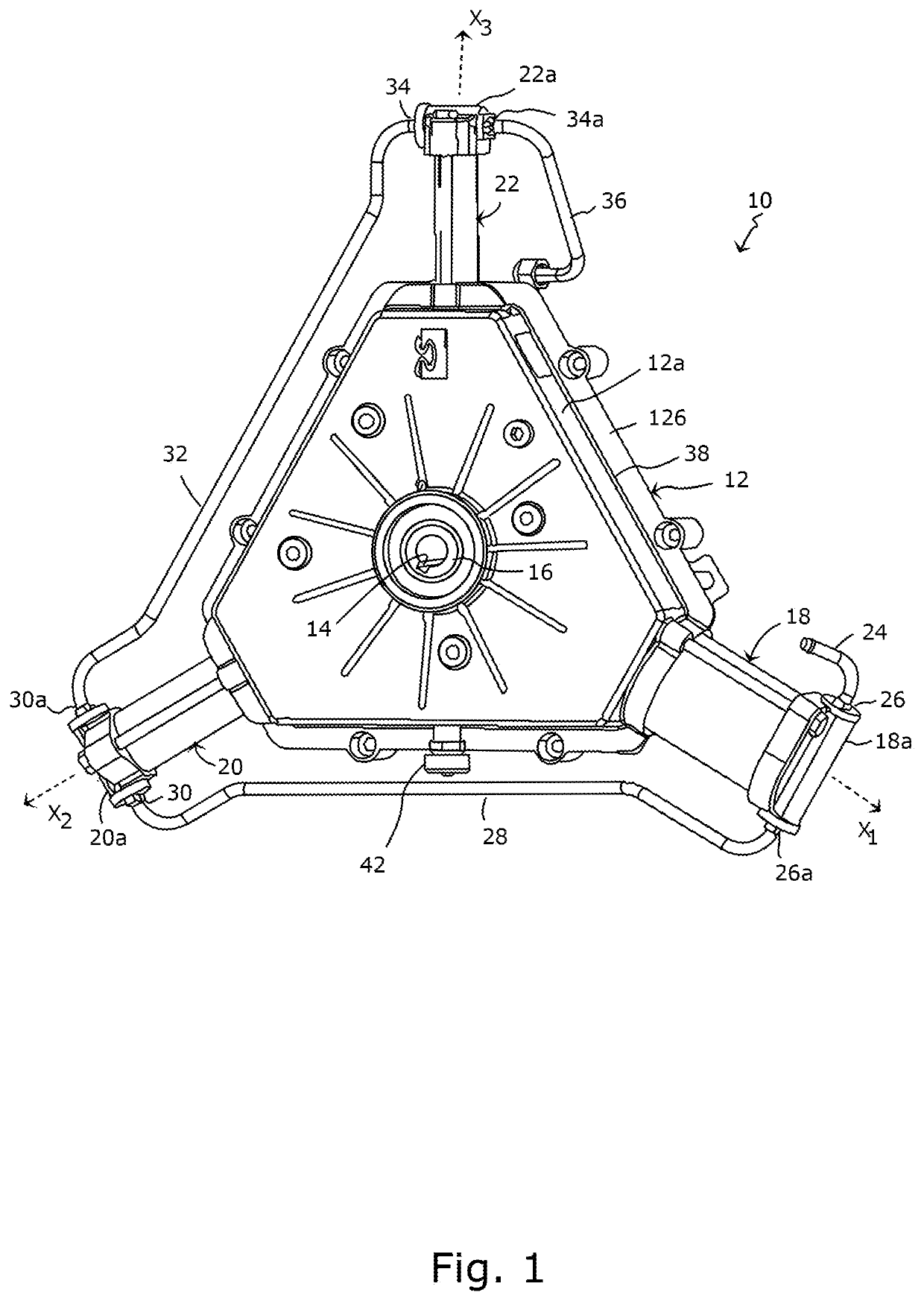
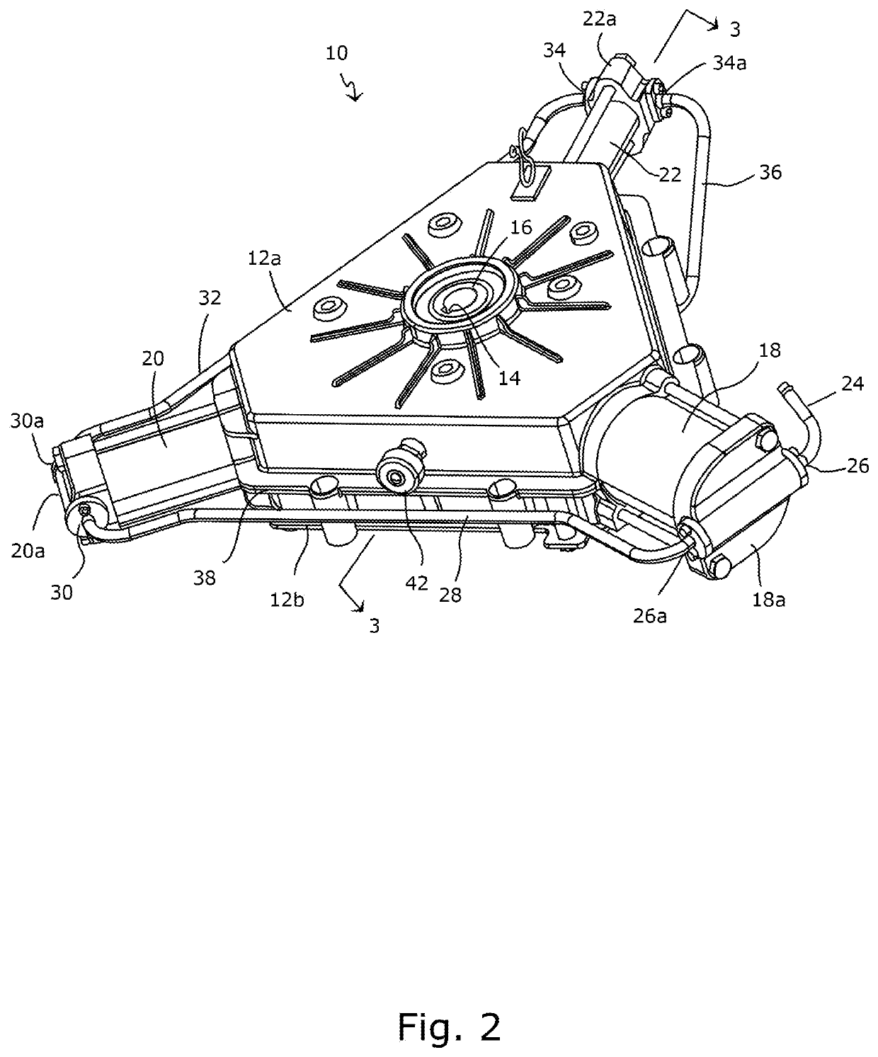
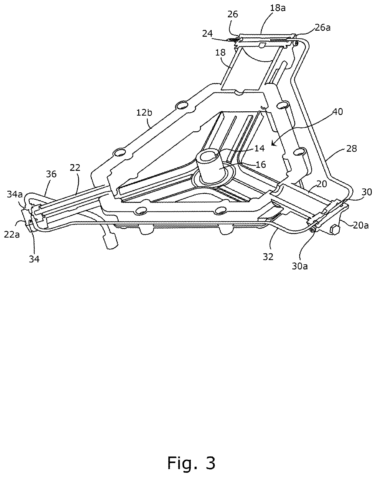
[0012]Referring to the drawings, there is seen in FIGS. 1 through 3 one embodiment of the inventive compressor assembly designated generally by the reference numeral 10. Compressor assembly 10 includes a housing 12 and is configured to connect to a motor and speed reducer (not shown) via keyed bore 14 in shaft sleeve 16. Compressor assembly 10 generally includes a housing 12 comprising a block comprised of corresponding block halves 12a and 12b. First, second and third stage cylinder 18, 20 and 22, respectively, are spaced 120° apart and radially extend along respective axes X1-X3.

[0013]For the sake of clarity, the moving components of the compressor have been removed. An example of such suitable components may be found within U.S. Pat. No. 8,684,704 (the '704 patent) assigned to Carleton Like Support Systems, Inc., the entirety of which is incorporated by reference as if fully set forth herein. As recounted within the '704 patent, a compressor may include a cam positioned on shaft ...


PUM


Abstract

A cam driven compressor includes a cam coupled to a plurality of cylinder and piston assemblies. Each cylinder and piston assembly comprises a piston located and movable within a respective cylinder. Each cylinder has a cylinder head. The compressor comprises a housing defining a cavity configured to receive a portion of a source gas from one or more of the cylinders in order to maintain a positive gas pressure within the cavity.

Description

BACKGROUND OF THE INVENTION[0001]The present invention relates to compressors and, in a first aspect thereof, more particularly relates to a compressor having a cavity at a positive internal pressure relative to the surrounding environment to reduce induction of contaminants into the product gas produced by the compressor. In another aspect, the invention relates to a compressor having a pressure relief valve in communication with the compressor cavity to maintain the compressor cavity at a desired positive pressure.[0002]Electrically driven compressors must convert rotary motion from a motor into linear motion to actuate a piston or a series of pistons to generate compressed gas. Most gas compressors accomplish this task by means of a crankshaft and connecting rod assembly similar to that found in internal combustion engines. By design, compressors known in the art will create a slight leak around the inter-stage seal located between the piston and cylinder. Some advantages to this...

Claims


Application Information

Patent Timeline
Patent Type & Authority Patents(United States)
IPC IPC(8): F04B25/00F04B41/00F04B27/04F04B27/053F04B27/08F04B27/10F04B27/12F04B37/12F04B49/22F04B53/10
CPCF04B49/22F04B25/00F04B27/0409F04B27/0414F04B27/0423F04B27/053F04B27/0878F04B27/0891F04B27/0895F04B27/1045F04B27/12F04B37/12F04B41/00F04B53/10
Inventor GOLDENSOPH, GERINBROWN, JEFF
Owner COBHAM MISSION SYST DAVENPORT LSS INC
Why Eureka
Try Eureka