Lane change assist apparatus for vehicle

a technology for assist devices and vehicles, applied in control devices, external condition input parameters, control devices, etc., can solve problems such as discomfort for drivers, inability to achieve stable lane change, and high calculation load for target trajectory, and achieve the effect of smoothing out the change of lanes

Active Publication Date: 2021-05-18
TOYOTA JIDOSHA KK
View PDF96 Cites 2 Cited by
  • Summary
  • Abstract
  • Description
  • Claims
  • Application Information

AI Technical Summary

Benefits of technology

[0021]Thus, according to one embodiment of the present invention, it is not necessary to successively (sequentially) and repeatedly determine / calculate the target trajectory function (even when the vehicle speed is varied). The target yaw state amount is successively (sequentially) calculated based on the target trajectory function calculated at the start of the lane change assist control, the acquired vehicle speed, and the elapse time from the start of the lane change assist control. Therefore, changing lanes smoothly can be performed, while reflecting the accelerator pedal operation performed by the driver and suppressing the calculation load.
[0057]According to the above aspect of the present invention, the target trajectory function can be obtained which can achieve smooth transition of the movement of the own vehicle in the lateral direction between the state at the start of the lane change assist control and the state at the completion of the lane change assist control. After the completion of the lane change assist control, it is possible to have the own vehicle travel according to (or in the vicinity of) the center position of the adjacent lane in the lane width direction as it is. Therefore, the own vehicle can be made to change lanes more smoothly.

Problems solved by technology

In this case, since the traveling state of the vehicle differs from the traveling state assumed when determining the target trajectory due to the change of the vehicle speed, stable lane change may not be achieved.
However, in such an apparatus, the calculation load for the target trajectory becomes high.
Further, there is a risk that the driver may feel discomfort due to the change of the target trajectory.

Method used


Image

  • Lane change assist apparatus for vehicle
  • Lane change assist apparatus for vehicle
  • Lane change assist apparatus for vehicle

Examples


Embodiment Construction

[0067]A lane change assist apparatus according to the present invention will next be described with reference to the drawings.

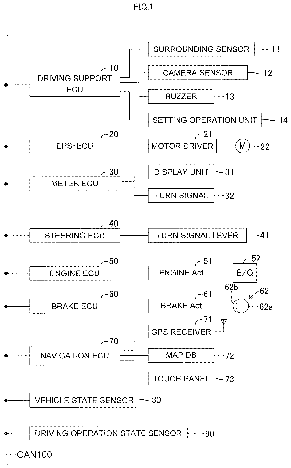
[0068]The lane change assist apparatus according to the embodiment of the present invention is applied to a vehicle (hereinafter also referred to as an “own vehicle” in order to be distinguished from other vehicles). The lane change assist apparatus, as illustrated in FIG. 1, includes a driving support (assist) ECU 10, an electric power steering ECU 20, a meter ECU 30, a steering ECU 40, an engine ECU 50, a brake ECU 60, and a navigation ECU 70.

[0069]Those ECUs are electric control units each including a microcomputer as a main part, and are connected to one another so as to be able to mutually transmit and receive information via a controller area network (CAN) 100. The microcomputer herein includes a CPU, a ROM, a RAM, a nonvolatile memory, an interface I / F, and the like. The CPU executes instructions (programs and routines) stored in the ROM to realize var...


PUM


Abstract

A driving support ECU initializes a target trajectory calculation parameter at a start of LCA; calculates, based on the target trajectory calculation parameter, a target trajectory function representing a target lateral position which is a target position of an own vehicle in a lane width direction in accordance with an elapsed time t from the start of LCA; successively calculates a target lateral movement state amount of the own vehicle based on the target trajectory function and the elapsed time t; calculates a target yaw state amount of the own vehicle based on the target lateral movement state amount and a vehicle speed; and calculates a target control amount based on the target yaw state amount and the target lateral position.

Description

BACKGROUND OF THE INVENTION1. Field of the Invention[0001]The present invention relates to a lane change assist apparatus for a vehicle configured to assist / support a steering operation for changing lanes.2. Description of the Related Art[0002]Conventionally, a lane change assist apparatus has been known which is configured to assist a steering operation (steering wheel operation) for changing lanes. Such a lane change assist apparatus calculates a target trajectory in such a manner that a vehicle changes a traveling direction of the own vehicle toward an adjacent lane being a destination of changing lanes. The lane change assist apparatus controls a steering angle of right and left steered wheels in such a manner that the vehicle travels along the calculated target trajectory.[0003]For example, an apparatus (hereinafter referred to as a “conventional apparatus”), as proposed in Japanese Patent Application Laid-Open (kokai) 2008-149855 A, successively (sequentially) calculates targe...

Claims


Application Information

Patent Timeline
Patent Type & Authority Patents(United States)
IPC IPC(8): B62D15/02B60W40/114
CPCB62D15/0255B60W40/114B60W2520/125B60W2520/14B60W30/18163B60W2520/10B60W2720/14B60W2710/20B60W2720/12B60W2720/125B60W30/12B60W2540/20B60W2540/215B60W2552/05B60W2554/00B60W2552/53
Inventor FUJII, SHOTA
Owner TOYOTA JIDOSHA KK
Why Eureka
Try Eureka