Image processing device, image processing method, and program processing image which is developed as a panorama
a technology of image processing and panorama, applied in the field of image processing device, image processing method, program processing image which is developed as a panorama, can solve problems such as large calculation processing load, and achieve the effect of suppressing the calculation load of resolution enhancement processing
- Summary
- Abstract
- Description
- Claims
- Application Information
AI Technical Summary
Benefits of technology
Problems solved by technology
Method used
Image
Examples
first embodiment
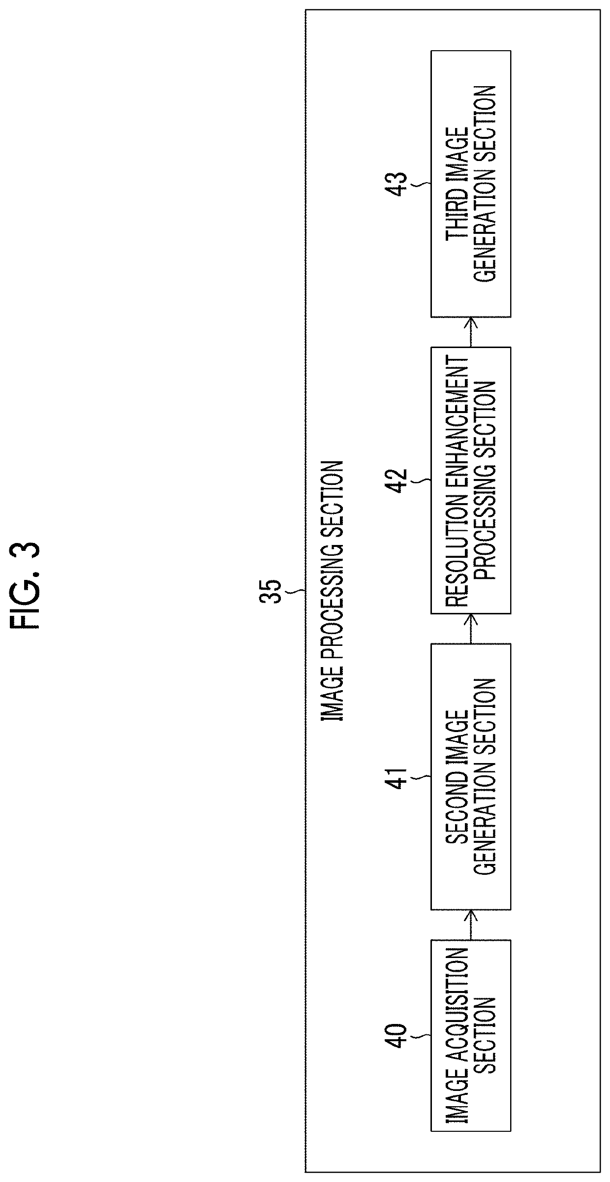
[0066]FIG. 3 is a functional block diagram illustrating a functional configuration example of the image processing section 35.
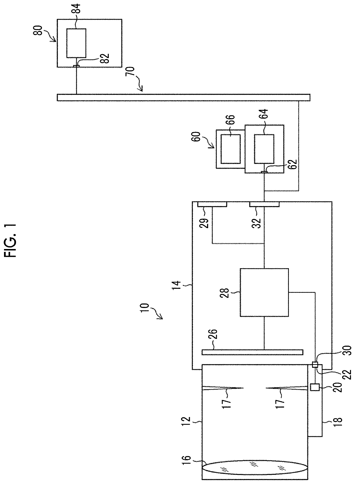
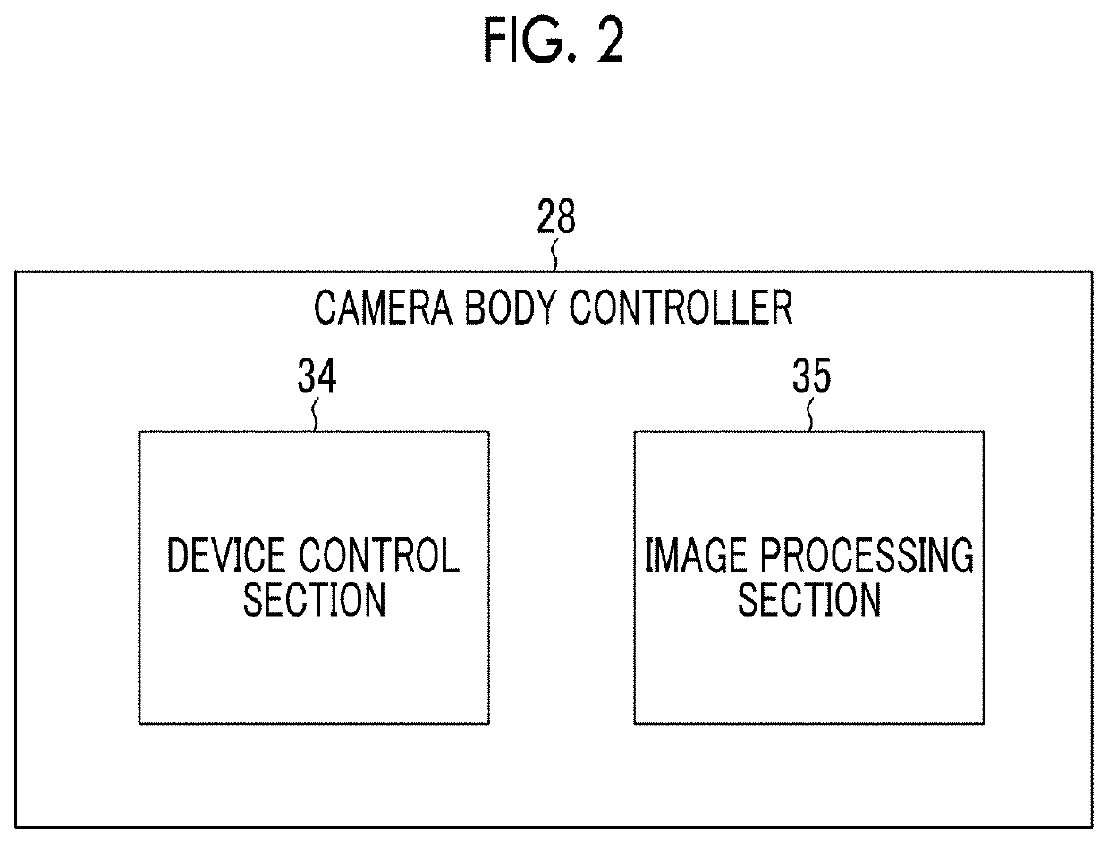
[0067]In addition to the above-mentioned functions, the image processing section 35 provided in the camera body controller 28 mentioned above comprises an image acquisition section 40, a second image generation section 41, a resolution enhancement processing section 42, and a third image generation section 43.
[0068]The image acquisition section 40 acquires a captured image (first image) acquired from the imaging element 26 by imaging the subject image using the optical system. Here, the captured image is based on the image data output from the imaging element 26 in a case where the subject image is captured, and it not particularly limited so long as the panorama development performed by the second image generation section 41 described later can be performed. For example, the image acquisition section 40 acquires image data, for which sensor correction proces...
second embodiment
[0098]Next, a second embodiment of the present invention will be described. In the present embodiment, resolution enhancement processing is performed on the panoramic developed image 52 on which the distortion correction has been performed.
[0099]FIG. 10 is a block diagram illustrating a functional configuration example of the image processing section 35 in the present embodiment. The image processing section 35 of the present embodiment is composed of the image acquisition section 40, the second image generation section 41, the distortion correction section 44, the resolution enhancement processing section 42, and the third image generation section 43. The same reference numerals and signs are given to the parts already described in FIG. 3, and the description is omitted.
[0100]Compared with the image processing section 35 shown in FIG. 3, the image processing section 35 of the present embodiment is provided with a distortion correction section 44 between the second image generation ...
modification example
[0106]Next, a modified example of the resolution enhancement processing section 42 will be described. The resolution enhancement processing section 42 of the present example changes the level of enhancement of the resolution enhancement processing in accordance with the position in the vertical direction of the second image, or performs resolution enhancement processing on only a partial area of the second image.
[0107]FIG. 12 is a diagram schematically illustrating the panoramic developed image 52. The resolution enhancement processing section 42 of the present example adjusts the level of enhancement of the resolution enhancement processing by changing the gain of the resolution enhancement processing using different filters in accordance with an area in the vertical direction of the panoramic developed image 52, for example.
[0108]For example, as shown in FIG. 12, the resolution enhancement processing section 42 performs resolution enhancement processing through the filter A, the f...
PUM
 Abstract
Description
Claims
Application Information
 - R&D
- Intellectual Property
- Life Sciences
- Materials
- Tech Scout
- Unparalleled Data Quality
- Higher Quality Content
- 60% Fewer Hallucinations
Browse by: Latest US Patents, China's latest patents, Technical Efficacy Thesaurus, Application Domain, Technology Topic, Popular Technical Reports.
© 2025 PatSnap. All rights reserved.Legal|Privacy policy|Modern Slavery Act Transparency Statement|Sitemap|About US| Contact US: help@patsnap.com


