Electric power steering apparatus

a technology of electric power steering and steering gear, which is applied in the direction of electric generator control, dynamo-electric converter control, dynamo-electric gear control, etc., can solve the problems of steering responsiveness reduction, and achieve the effect of favorable steering responsiveness and reduction of calculation load

Active Publication Date: 2016-07-05
JTEKT CORP
View PDF12 Cites 4 Cited by
  • Summary
  • Abstract
  • Description
  • Claims
  • Application Information

AI Technical Summary

Benefits of technology

[0006]The invention provides an electric power steering apparatus that is capable of lightening a calculation load of a control device for performing synchronization control on a two-system motor, and that exhibits a high degree of steering responsiveness.
[0008]According to the aspect described above, the second command value, which is calculated by the second command value calculating means on the basis of the first command value calculated by the first command value calculating means and the current value obtained by causing the motor driving system current adding means to add together the currents of the respective motor driving systems, is output to the plurality of motor driving systems as the motor control command. Hence, the calculation performed by the second command value calculating means is not complicated, and as a result, a calculation load thereof can be reduced.
[0010]According to the aspect described above, the second command value can be output to the respective motor drive circuits of the two systems through the d / q coordinate system current feedback calculation. As a result, a calculation load of a control device can be lightened, and the two-system electric motor can be subjected to appropriate synchronization control under any travel conditions. Hence, an assist force that provides a favorable steering feeling is obtained.
[0012]According to the aspect described above, the second command value can be output to the respective motor drive circuits of the two systems through the d / q coordinate system current feedback calculation by adding together the respective current values of the two systems. As a result, the calculation load of the control device can be lightened by adding together the respective current values of the two systems after subjecting the respective current values to three phase / two phase conversion individually, and therefore the two-system electric motor can be subjected to appropriate synchronization control under any travel conditions. Hence, an assist force that provides a favorable steering feeling is obtained.
[0015]According to the aspect described above, when an abnormality occurs in the electric motor in one of the two systems or in one of the motor drive circuits, assistance can be continued by the system in which the abnormality has not occurred. As a result, rapid deterioration of the steering feeling can be prevented.
[0017]According to the aspects described above, it is possible to provide an electric power steering apparatus with which a reduction in a calculation load can be achieved. Further, according to the aspects described above, it is possible to provide an electric power steering apparatus capable of appropriately controlling a two-system motor synchronously such that a favorable steering responsiveness is obtained.

Problems solved by technology

When the calculation load increases, appropriate synchronization control for the vehicle condition cannot be performed, and therefore a tracking delay may occur, leading to a reduction in steering responsiveness.

Method used


Image

  • Electric power steering apparatus
  • Electric power steering apparatus
  • Electric power steering apparatus

Examples


first embodiment

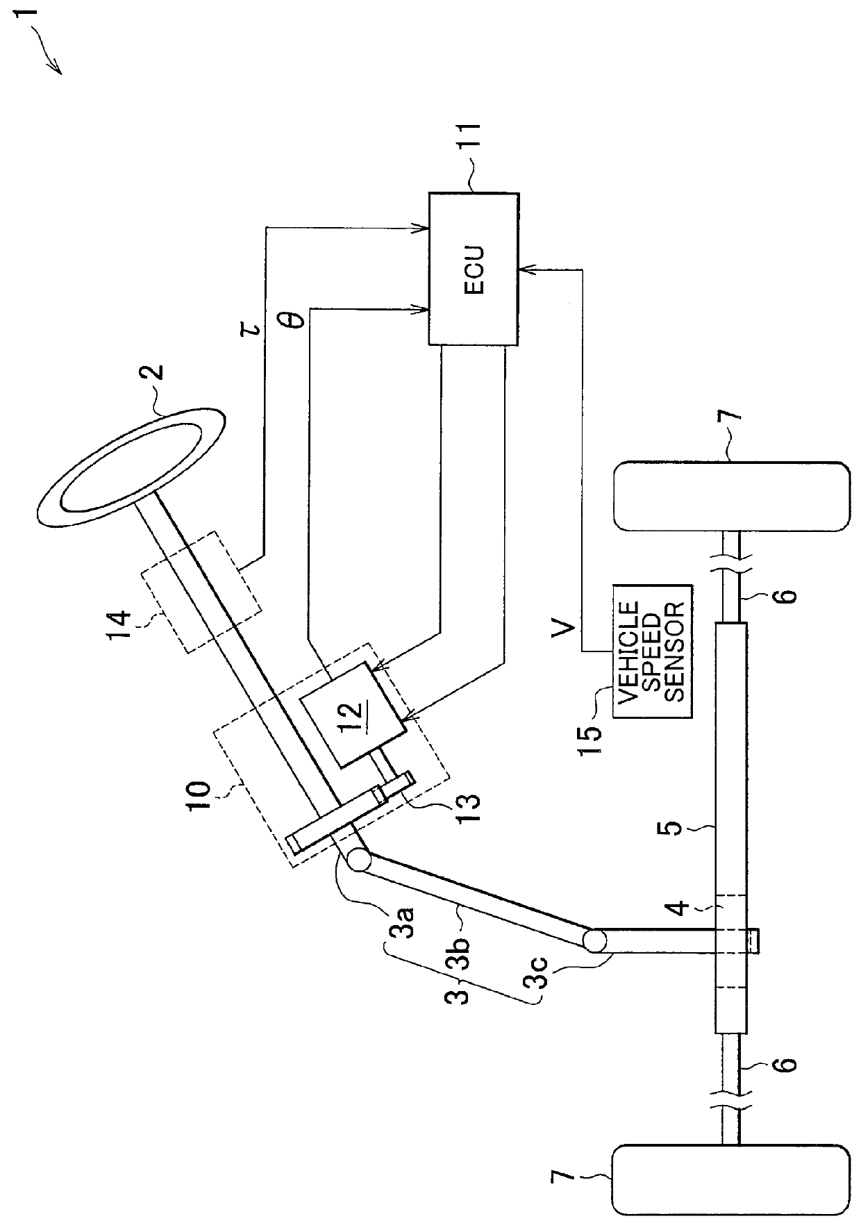
[0026]an electric power steering apparatus (EPS) employing a two-system motor according to the invention will be described below with reference to the drawings. As shown in FIG. 1, in an EPS 1 according to the first embodiment, a steering shaft 3, to which a steering wheel 2 is fixed, is coupled to a rack shaft 5 via a rack and pinion mechanism 4.

[0027]Rotation of the steering shaft 3 accompanying a steering operation is converted into a reciprocating linear motion of the rack shaft 5 by the rack and pinion mechanism 4. Note that the steering shaft 3 according to the first embodiment is formed by coupling a column shaft 3a, an intermediate shaft 3b, and a pinion shaft 3c. The reciprocating linear motion of the rack shaft 5 accompanying rotation of the steering shaft 3 is transmitted to a knuckle, not shown in the drawing, via a tie rod 6 coupled to either end of the rack shaft 5, and as a result, a steering angle of a steered wheel 7, or in other words an advancement direction of a ...

second embodiment

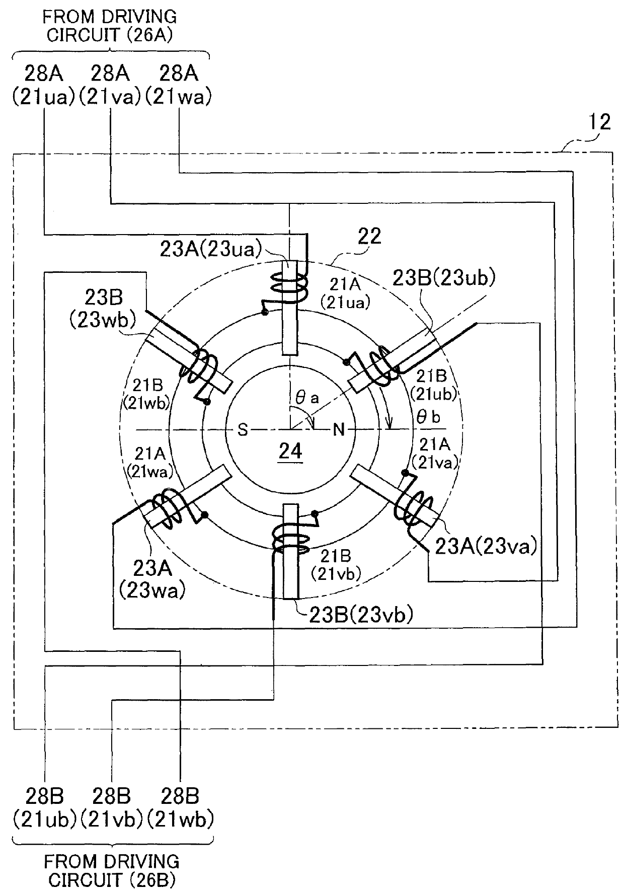
[0051]In other words, in the motor 12 the first system motor coil 21A and the second system motor coil 21B of the two systems share the stator 22 and the rotor 24. The rotor 24 rotates on the basis of the magnetomotive force generated by the first system motor coil 21A and the second system motor coil 21B wound around the teeth 23 (23u, 23v, 23w) in the manner described above.

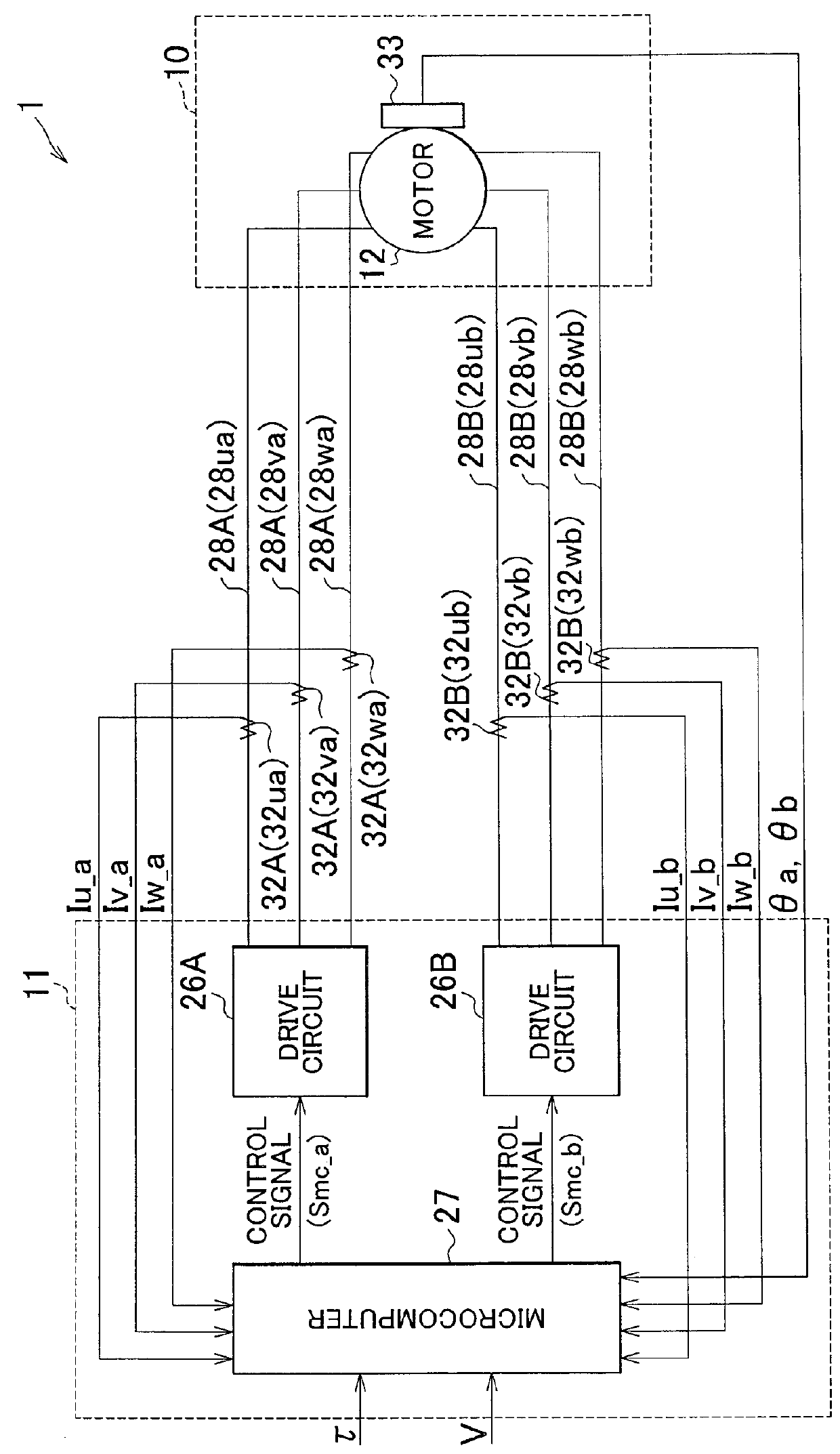
[0052]The ECU 11 according to the second embodiment is configured to control a motor torque by supplying drive power independently to the first system motor coil 21A and the second system motor coil 21B.

[0053]As shown in FIG. 6, the ECU 11 according to the second embodiment includes two motor drive circuits, namely a first system motor drive circuit 26A and a second system motor drive circuit 26B, provided independently with respect to the first system motor coil 21A and the second system motor coil 21B. Further, the ECU 11 includes a microcomputer 27 that serves as control means for outputting a first system ...


PUM


Abstract

Motor control command output means outputs, as a motor control command, a second command value, which is calculated by second command value calculating means on the basis of a first command value generated by first command value calculating means and a current value obtained by causing motor driving system current adding means to add together currents of respective motor driving systems, to the motor driving systems of two systems constituted by a motor and drive circuits for driving the motor. The second command value calculating means may calculate the second command value by performing a d / q coordinate system current feedback calculation using the current value.

Description

BACKGROUND OF THE INVENTION[0001]1. Field of the Invention[0002]The invention relates to an electric power steering apparatus.[0003]2. Description of Related Art[0004]Japanese Patent Application Publication No. 2004-10024 (JP-A-2004-10024) describes an electric power steering apparatus (EPS) that modifies steering angles of steered wheels by driving two motors to rotate. The EPS described in JP-A-2004-10024 controls a first motor and a second motor independently using a first drive circuit and a first control device, and a second drive circuit and a second control device, respectively. In other words, the steering angles of the steered wheels are modified by controlling the motors of two systems independently.[0005]In the EPS described in JP-A-2004-10024, however, although the respective motors, drive circuits, and control devices of the two systems are controlled independently, the two motors must be driven using appropriate synchronization control in order to modify the steering a...

Claims


Application Information

Patent Timeline
Patent Type & Authority Patents(United States)
IPC IPC(8): H02P31/00B62D5/04H02P6/00H02P21/06H02P25/22
CPCH02P31/00B62D5/0403B62D5/046B62D5/0463H02P21/06H02P25/22
Inventor SUZUKI, HIROSHI
Owner JTEKT CORP
Why Eureka
Try Eureka