
Nuclear power generation system

a technology of nuclear power generation and nuclear power, which is applied in the field of nuclear power generation systems, can solve the problems of increasing the height and volume of the containment, increasing the construction cost, and high installation costs of polar cranes, so as to reduce the size of the containment structure, reduce the footprint of the system, and reduce the length of the ducting connection

Active Publication Date: 2021-06-01
ROLLS-ROYCE SMR LTD
View PDF8 Cites 0 Cited by
  • Summary
  • Abstract
  • Description
  • Claims
  • Application Information

AI Technical Summary

Benefits of technology

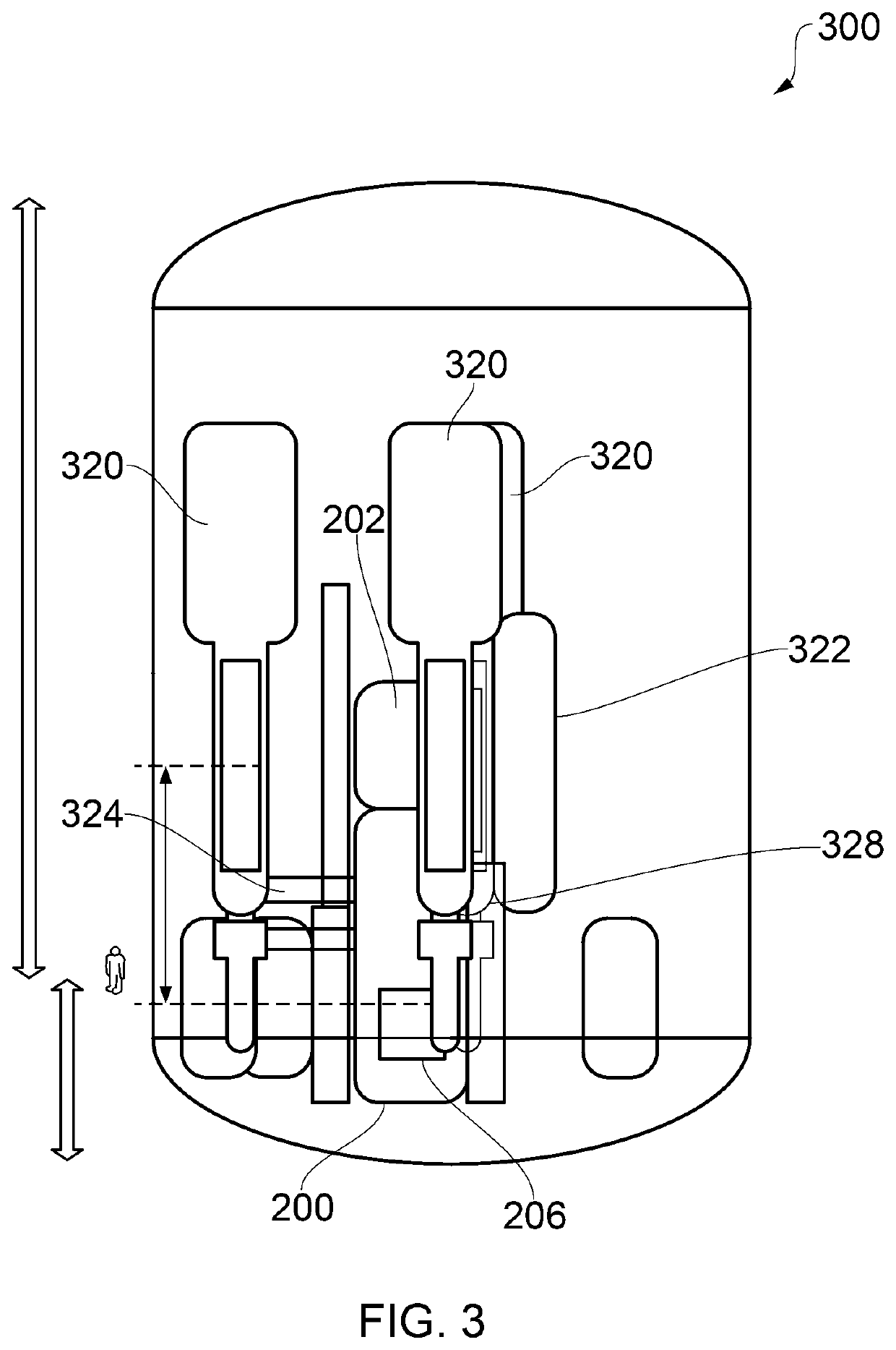
[0021]By providing first and second crane gantries which have a fixed radial orientation relative to the reactor vessel and which thus define fixed fuel rod and component paths respectively, the rotating polar crane arrangement of the prior art is dispensed with along with its associated problems. For example, the radially fixed gantries will be easier and therefore less costly to install. Furthermore, because the crane gantries do not rotate, they do not trace out a circular / angular path around the reactor vessel, and so the circumferential damage risk area around the reactor vessel is effectively eliminated. Components of the nuclear power generation system (e.g. steam generator, pressuriser, etc.) can therefore be mounted close to the reactor vessel thus reducing the footprint of the system (and the length of the ducting connecting the components). Furthermore, the crane gantries can be mounted at a lower height than in the prior art (as they don't need to rotate above the system components) thus further reducing the size of the containment structure and reducing weight at elevated height.
[0022]Furthermore, because each gantry may have its own dedicated hoist, it is not necessary to change between different attachment tools so that maintenance and refuelling so that system down-times are reduced.
[0050]In some embodiments, the reactor vessel is surrounded by a central support monolith e.g. circumferentially surrounding the reactor vessel. The central monolith may be used to support the radially innermost ends of the gantries. The increased proximity of the components of the nuclear power generation system (in particular the steam generators and pressurisers) to the reactor vessel means that they can also be mounted directly to the central monolith. Structural stability of the reactor is thereby improved. The central support monolith may further comprise one or more spokes which may extend radially from the portion circumferentially surrounding the reactor vessel.
[0054]The provision of a central support monolith with spoke portions allows mounting of both the reactor system components and the crane gantries which simplifies the construction of the reactor system compared to the prior art systems which requires separate mounting systems for the components and the polar crane.

Problems solved by technology

This makes polar cranes expensive to install.
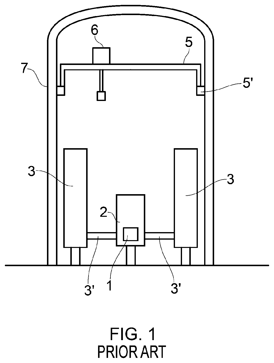
Any components of the nuclear power generation system (e.g. steam generators, pressuriser, etc.) mounted in a ‘damage risk area’ around the reactor vessel are therefore at risk of damage from impact with the crane tool attachments.
As a result, in the known systems:i. the polar crane arrangement is positioned high above the reactor vessel and steam generators to mitigate the risk of contact between the hoist tool attachments and the system components—this increases the height and volume (and thus construction cost) of the containment structure 7—furthermore, the elevated position of the polar crane (which is 100s of tonnes in weight) presents a substantial engineering challenge particularly in terms of seismic resilience; andii. steam generators and the pressuriser are radially spaced from the reactor vessel, so that they are not within the damage risk area.
This increases the length of ducts carrying pressurised water between the reactor vessel and the steam generators / pressuriser, and also increases the total diameter of the nuclear reactor, which further increases the cost of construction of the containment structure 7.
The need to change between these various tool attachments increases the down-time of the system when performing maintenance and refuelling.

Method used


Image

  • Nuclear power generation system
  • Nuclear power generation system
  • Nuclear power generation system

Examples


Embodiment Construction

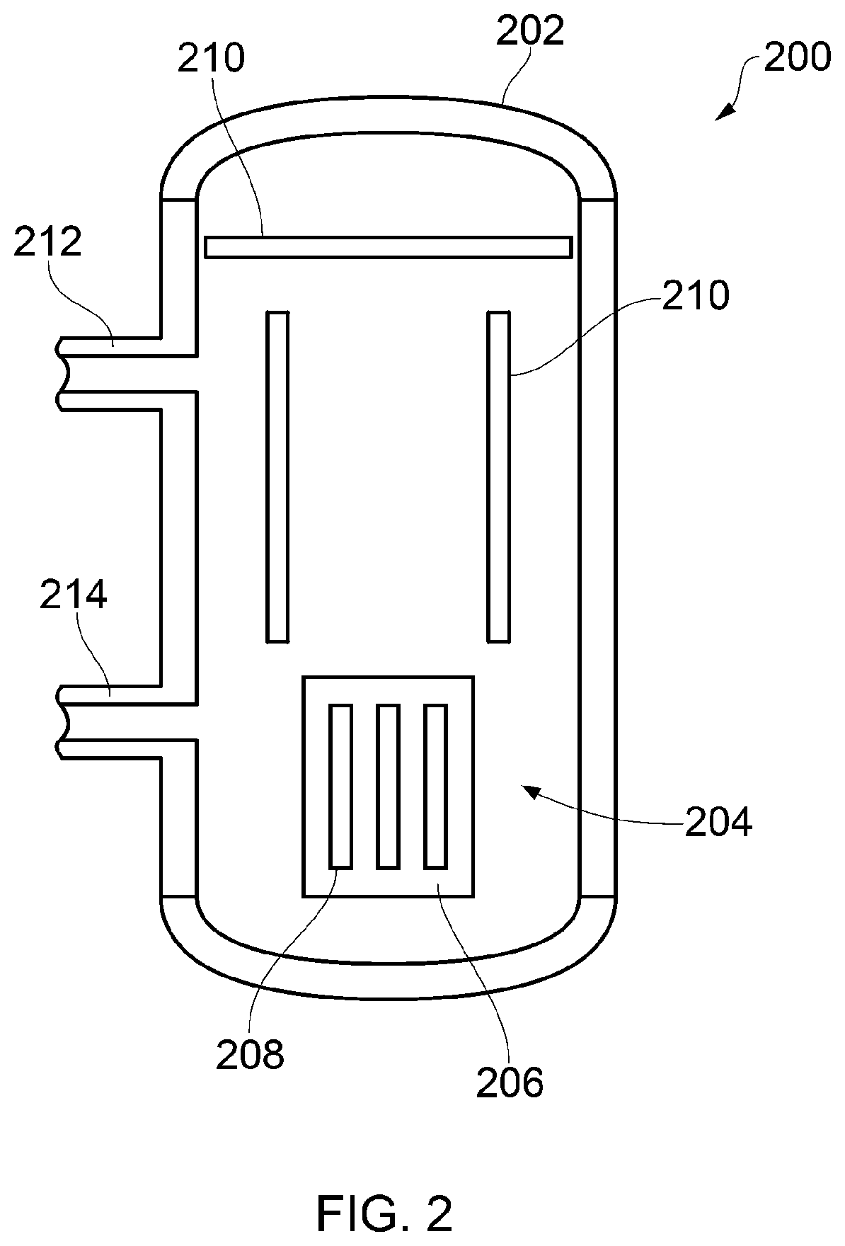
[0066]FIG. 2 shows a pressurised reactor vessel 200 for use in a nuclear power generation system of the pressurised water reactor (PWR) type. The reactor vessel 200 has a removable reactor head 202 for closing an upper opening in the reactor vessel 200 in use, thereby establishing a pressure boundary. The interior 204 of the reactor vessel 200 contains a reactor core 206 for holding nuclear fuel rods 208, and reactor vessel internal components 210. In use, the reactor vessel is filled with pressurised water.

[0067]A fluid outlet 212 is provided in a side-wall of the reactor vessel for transfer of hot pressurised water from the reactor vessel to a steam generator (not shown). A fluid inlet 214 is also provided in the side-wall of the reactor vessel for transfer of cool pressurised water back from the steam generator. As shown, the fluid outlet is positioned vertically above the fluid inlet. If more than one steam generator is used, then further inlets and outlets may be provided.

[0068...


PUM


Abstract

The nuclear power generation system of the present invention comprises a reactor vessel. It further comprises a first crane gantry defining a fuel rod path along which nuclear fuel rods can be moved to / from the reactor vessel and a second crane gantry defining a component path along which reactor vessel components can be moved to / from the reactor vessel. The the first and second crane gantries both have a fixed radial orientation relative to the reactor vessel.

Description

[0001]This disclosure claims the benefit of UK Patent Application No. GB 1719715.3, filed on 28 Nov. 2017, which is hereby incorporated herein in its entirety.FIELD OF INVENTION[0002]The present invention relates to a nuclear power generation system including crane gantries for maintenance and refuelling; and to a method of performing maintenance and refuelling operations in a nuclear power generation system.BACKGROUND[0003]Maintenance and refuelling is an important part of the operation of a nuclear power generation system. Maintenance is required periodically, e.g. to replace old and / or damaged parts of the system. Refuelling is required periodically, in order to replace spent fuel rods.[0004]When performing maintenance / refuelling of a reactor vessel, it is necessary to remove at least the reactor vessel head from the reactor vessel, thereby revealing an interior of the reactor vessel. When performing refuelling, it is also necessary to remove some of the internal components of th...

Claims


Application Information

Patent Timeline
Patent Type & Authority Patents(United States)
IPC IPC(8): G21C19/18B66C17/06G21C19/20G21C19/32B66C19/00
CPCG21C19/18B66C17/06B66C19/007G21C19/20G21C19/207G21C19/32Y02E30/30B66C7/02B66C19/00G21C13/02
Inventor GOODFELLOW, MARTIN J
Owner ROLLS-ROYCE SMR LTD
Learn More