Supercharge Your Innovation With Domain-Expert AI Agents!

Optimizing MRC coefficients for RAKE receiver for increasing SNR

a rake receiver and mrc coefficient technology, applied in the field of rake receivers, can solve the problems of not knowing the exact cir vector h at the receiver, not knowing the n in the practical receiver, and not maximizing the received snr

Active Publication Date: 2021-06-01
NXP BV
View PDF24 Cites 0 Cited by
  • Summary
  • Abstract
  • Description
  • Claims
  • Application Information

AI Technical Summary

Benefits of technology

The patent describes a method of improving the quality of a received signal by adjusting the estimates of the signal's components. This is done by multiplying the estimates with individual correction factors that are derived from the signal and noise levels. This process makes it easier for receivers to calculate the improved signal quality and can be performed quickly and easily. The technical effect is to improve signal quality in a simple and efficient way.

Problems solved by technology

If h is a CIR vector, then the linear coefficients that maximize the received SNR are obtained as the complex conjugate h* of the channel vector h. However, it is a fundamental problem that the exact CIR vector h is not known at the receiver.
Unfortunately, n is not known in a practical receiver.
Therefore, multiplying the received signal vector with the complex conjugate of ĥ (i.e. the estimated channel or CIR) will not maximize the received SNR.

Method used


Image

  • Optimizing MRC coefficients for RAKE receiver for increasing SNR
  • Optimizing MRC coefficients for RAKE receiver for increasing SNR

Examples


Embodiment Construction

[0027]The illustration in the drawing is schematic. It is noted that in different figures, similar or identical elements are provided with the same reference signs or with reference signs, which differ only within the first digit.

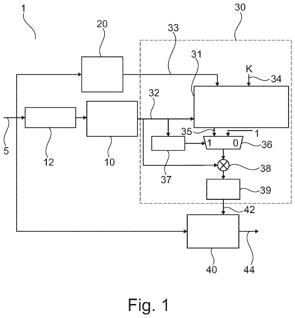
[0028]FIG. 1 shows an UWB receiver 1 in accordance with an embodiment. More specifically, the receiver 1 comprises a data signal input 5, a channel estimation unit 10, a correlator 12, a noise variance estimating unit 20, a device 30 for determining MRC coefficients, and a RAKE receiver 40 having an MRC input 42 and a receiver output 44. The device 30 comprises a processing unit 31 coupled to receive an estimated channel impulse response vector 32 from the channel estimation unit 10, an estimated noise variance vector 33 from the noise variance estimating unit 20, and a predetermined scalar value K at input 34. The processing unit 31 is adapted to calculate multiplication factors (or a multiplication factor vector) based on the estimated channel impulse res...


PUM


Abstract

There is described a method of determining an MRC coefficient vector for a RAKE receiver. The method comprises (a) estimating a channel impulse response vector, (b) estimating a noise variance vector, (c) calculating a multiplication factor vector based on the estimated channel impulse response vector and the estimated noise variance vector, (d) calculating a modified channel impulse response vector by multiplying each element in the estimated channel response vector with a corresponding element in the multiplication factor vector, and (e) calculating the MRC coefficient vector as the complex conjugate of the modified channel impulse response vector. There is also described a corresponding device, an UWB receiver, a computer program and a computer program product.

Description

CROSS-REFERENCE TO RELATED APPLICATIONS[0001]This application claims priority under 35 U.S.C. § 119 to European Patent Application No. 18202079.2, filed on Oct. 23, 2018, the contents of which are incorporated by reference herein.FIELD OF THE INVENTION[0002]The present invention relates to the field of RAKE receivers, in particular to a method and device for determining maximal ratio combiner (MRC) coefficients for a RAKE receiver. Furthermore, the present invention relates to a corresponding computer program and computer program product.ART BACKGROUND[0003]For UWB (ultra wide band) transceivers based on the IEEE 802.15.4a standard, a RAKE receiver is a good linear option to optimally combine the CIR (channel impulse response) with the received data such that the receiver obtains a combined signal which ensures a maximum SNR (signal to noise ratio). This is because a RAKE receiver uses the MRC (maximal ratio combiner) principle to coherently combine the CIR (or “fingers”) along with...

Claims


Application Information

Patent Timeline
Patent Type & Authority Patents(United States)
IPC IPC(8): H04B1/712H04B7/06H04L1/20H04L25/02
CPCH04B1/712H04B7/0634H04L1/203H04L25/0214
Inventor DUTTA, AMIT KUMARSRINIVASAN, RADHAAREEF, MOHAMMAD
Owner NXP BV
Features
  • R&D
  • Intellectual Property
  • Life Sciences
  • Materials
  • Tech Scout
  • Unparalleled Data Quality
  • Higher Quality Content
  • 60% Fewer Hallucinations
Learn More