Methods and systems for controlling ion contamination

a technology of ion contamination and methods, applied in the field of mass spectrometry, can solve the problems of increasing costs or reducing throughput, interfering with mass spectrometric analysis, and accelerating the contamination of mass analyzers, and achieves the effects of reducing the number of ion sources

Active Publication Date: 2021-06-08
DH TECH DEVMENT PTE
View PDF11 Cites 0 Cited by
  • Summary
  • Abstract
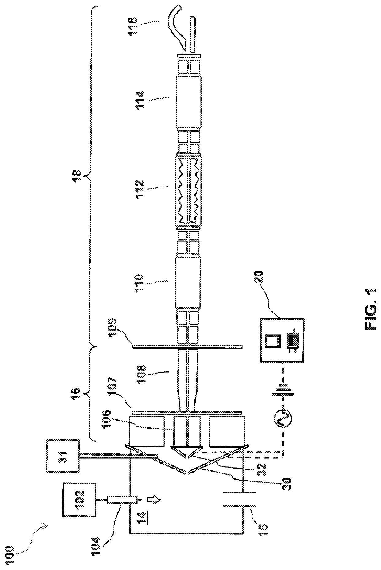
  • Description
  • Claims
  • Application Information

AI Technical Summary

Benefits of technology

[0006]Because most ion optics (e.g., lenses) of mass spectrometry systems are subject to ion deposition due to the defocusing of the ions during transmission therethrough and may exhibit significantly different behavior following substantial contamination (e.g., loss of sensitivity), fouled surfaces must be regularly cleaned to maintain sensitivity. While the surfaces of front-end components (e.g., curtain plates, orifice plates, Qjet, IQ0) may be relatively easy to clean, the fouling of components contained within the downstream high-vacuum chambers (e.g., Q0, Q1, IQ1) can result in substantial time and / or expense as the vacuum chambers must be vented and substantially disassembled prior to cleaning. Methods and systems for controlling contamination of components contained within the high-vacuum chambers of mass spectrometer systems are provided herein, and in some aspects, while maintaining the stability of the ion source and / or while continuously producing ions thereby. By reducing the transmission of ions into the sensitive components housed deep within the mass spectrometer, the present teachings can increase throughput, improve robustness, and / or decrease the downtime typically required to vent / disassemble / clean the fouled components.
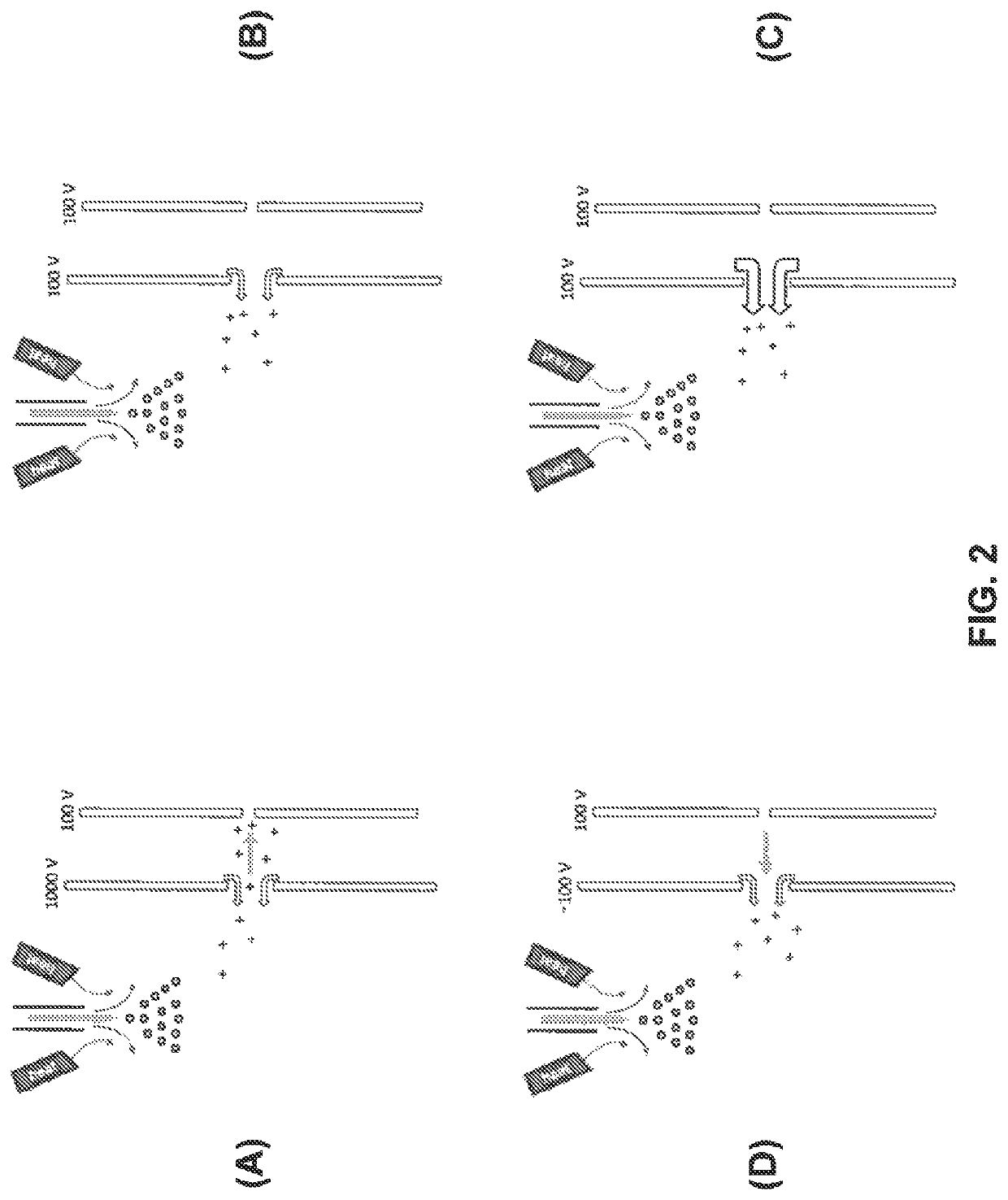
[0007]In accordance with various aspects of the present teachings, a mass spectrometer system is provided that comprises an ion source housing defining an ionization chamber, the ionization chamber comprising a curtain plate defining a curtain plate aperture through which ions generated in the ionization chamber can be transmitted to one or more downstream mass analyzers. An orifice plate defining a sampling orifice is separated from the curtain plate so as to define a curtain chamber therebetween through which ions from the curtain plate aperture can be transmitted to the sampling orifice. The system also includes a power supply electrically coupled to the curtain plate and the orifice plate for providing electrical signals thereto and a controller operatively coupled to the power supply, the controller being configured to control the electrical signals applied to the curtain plate and orifice plate so as to modulate the electric field within the curtain chamber from a first configuration during a first period in which ions are preferentially transmitted through the sampling orifice and a second configuration during a second period in which ions are substantially prevented from passing through the curtain chamber to the sampling orifice.

Problems solved by technology

Transmission of undesired ions and neutral molecules can foul / contaminate these downstream elements, thereby interfering with mass spectrometric analysis and / or leading to increased costs or decreased throughput necessitated by the cleaning of critical components within the high-vacuum chamber(s).
Additionally, some ion sources (e.g., electrospray sources for generating ions throughout a liquid chromatography elution gradient) can continuously generate ions that enter the mass analyzer even during the time periods when no data is collected or no analyte of interest would be present, further accelerating the contamination of the mass analyzer.
While the surfaces of front-end components (e.g., curtain plates, orifice plates, Qjet, IQ0) may be relatively easy to clean, the fouling of components contained within the downstream high-vacuum chambers (e.g., Q0, Q1, IQ1) can result in substantial time and / or expense as the vacuum chambers must be vented and substantially disassembled prior to cleaning.

Method used


Image

  • Methods and systems for controlling ion contamination
  • Methods and systems for controlling ion contamination
  • Methods and systems for controlling ion contamination

Examples


example 1

[0046]With reference now to FIGS. 4A-C, this infusion experiment demonstrates a substantial reduction in the number of ions transmitted into the high vacuum components of a mass spectrometer system operated in accordance with various aspects of the present teachings. A sample of reserpine 10 pg / μL was infused on a QTRAP® 6500 Q-q-Q mass spectrometer modified in accordance with the present teachings in which the orifice plate voltage was set to 100 V DC and the curtain plate was adjusted between a value of 1000 V DC and 100 V DC at various points during the infusion. FIG. 4A depicts the total ion current (TIC) detected at each time point over the course of the infusion, with the curtain plate voltage being adjusted to 100 V DC at approximately the following times: 0.3-0.4 min; 0.8-1.1 min; 1.4-1.6 min; and 2.0-2.3 min. As seen in FIG. 4A, the modulation of the curtain plate voltage to the same potential as the orifice plate was effective to block substantially all of the charged spec...


PUM

PropertyMeasurementUnit
voltageaaaaaaaaaa
voltageaaaaaaaaaa
voltageaaaaaaaaaa

Abstract

Because most ion optics of mass spectrometry systems are subject to ion deposition and may exhibit significantly different behavior following substantial contamination (e.g., loss of sensitivity), fouled surfaces must be regularly cleaned to maintain sensitivity. While the surfaces of front-end components (e.g., curtain plates, orifice plates, Qjet, Q0, IQ0) may be relatively easy to clean, the fouling of components contained within the downstream high-vacuum chambers (e.g., Q1, IQ1) can incur substantial delays and expense as the high-vacuum chambers must be vented and substantially disassembled prior to cleaning. Methods and systems for controlling contamination of components of mass spectrometer systems are provided herein. By reducing the transmission of contaminating ions during non-data acquisition periods, the present teachings can increase throughput, improve robustness, and / or decrease the downtime typically required to vent / disassemble / clean the fouled components.

Description

RELATED APPLICATION[0001]This application claims priority to U.S. provisional application No. 62 / 397,202, filed on Sep. 20, 2016, entitled “Methods and Systems for Controlling Ion Contamination,” which is incorporated herein by reference in its entirety.FIELD[0002]The present teachings are directed to mass spectrometry, and more particularly to methods and systems for controlling and / or reducing ion flux being transmitted into the high vacuum portions of a mass spectrometer.INTRODUCTION[0003]Mass spectrometry (MS) is an analytical technique for determining the elemental composition of test substances with both quantitative and qualitative applications. For example, MS can be used to identify unknown compounds, to determine the isotopic composition of elements in a molecule, and to determine the structure of a particular compound by observing its fragmentation, as well as to quantify the amount of a particular compound in the sample.[0004]In mass spectrometry, sample molecules are ge...

Claims


Application Information

Patent Timeline
Patent Type & Authority Patents(United States)
IPC IPC(8): H01J49/06G01N30/72G01N30/84
CPCH01J49/067G01N30/7233G01N30/84
Inventor COVEY, THOMAS R.LEBLANC, YVESSCHNEIDER, BRADLEY B.
Owner DH TECH DEVMENT PTE
Why Eureka
Try Eureka