Ultrasonic measuring device having transducers housed in a clamping device

a technology of ultrasonic and clamping device, which is applied in the direction of material analysis using sonic/ultrasonic/infrasonic waves, liquid/fluent solid measurement, volume variation compensation/correction apparatus, etc., can solve the problems of limiting the accuracy of ultrasonic measurement, interfering with ultrasonic measurement, etc., and achieves high or strong attenuation

Active Publication Date: 2021-06-29
LEVITRONIX
View PDF39 Cites 4 Cited by
  • Summary
  • Abstract
  • Description
  • Claims
  • Application Information

AI Technical Summary

Benefits of technology

[0011]Starting from the state of the art, it is therefore an object of the invention to propose an ultrasonic measuring device for the measurement on a fluid flowing in a pipe, which allows a very accurate determination of parameters, which are dependent on the sound propagation in the fluid. Furthermore, it is an object of the invention to propose a corresponding method for the ultrasonic measurement on a fluid flowing in a pipe.
[0035]In procedural terms, it is a further preferred measure that a continuous ultrasonic signal is emitted with at least one ultrasonic transducer, the amplitude of said signal is substantially constant over a predeterminable period of time. With this measure, the ultrasonic signal has a substantially constant amplitude over a longer period of time. Compared to a short ultrasonic pulse, this has the advantage that a higher resolution can be achieved, that the transient components, i.e. in particular the settling and decay processes, practically no longer influence the measurement, and that the simultaneous emitting and receiving of ultrasonic signals is significantly less sensitive to interference effects, such as turbulences in the fluid, temperature fluctuations, etc.

Problems solved by technology

The commonly used pipes, e.g. plastic hoses, are known with regard to their nominal dimensions (e.g. wall thickness, diameter) or with regard to the material, but however, deviations between individual hoses can occur time and again, which can interfere with the ultrasonic measurement or which can limit its accuracy.

Method used


Image

  • Ultrasonic measuring device having transducers housed in a clamping device
  • Ultrasonic measuring device having transducers housed in a clamping device
  • Ultrasonic measuring device having transducers housed in a clamping device

Examples


first embodiment

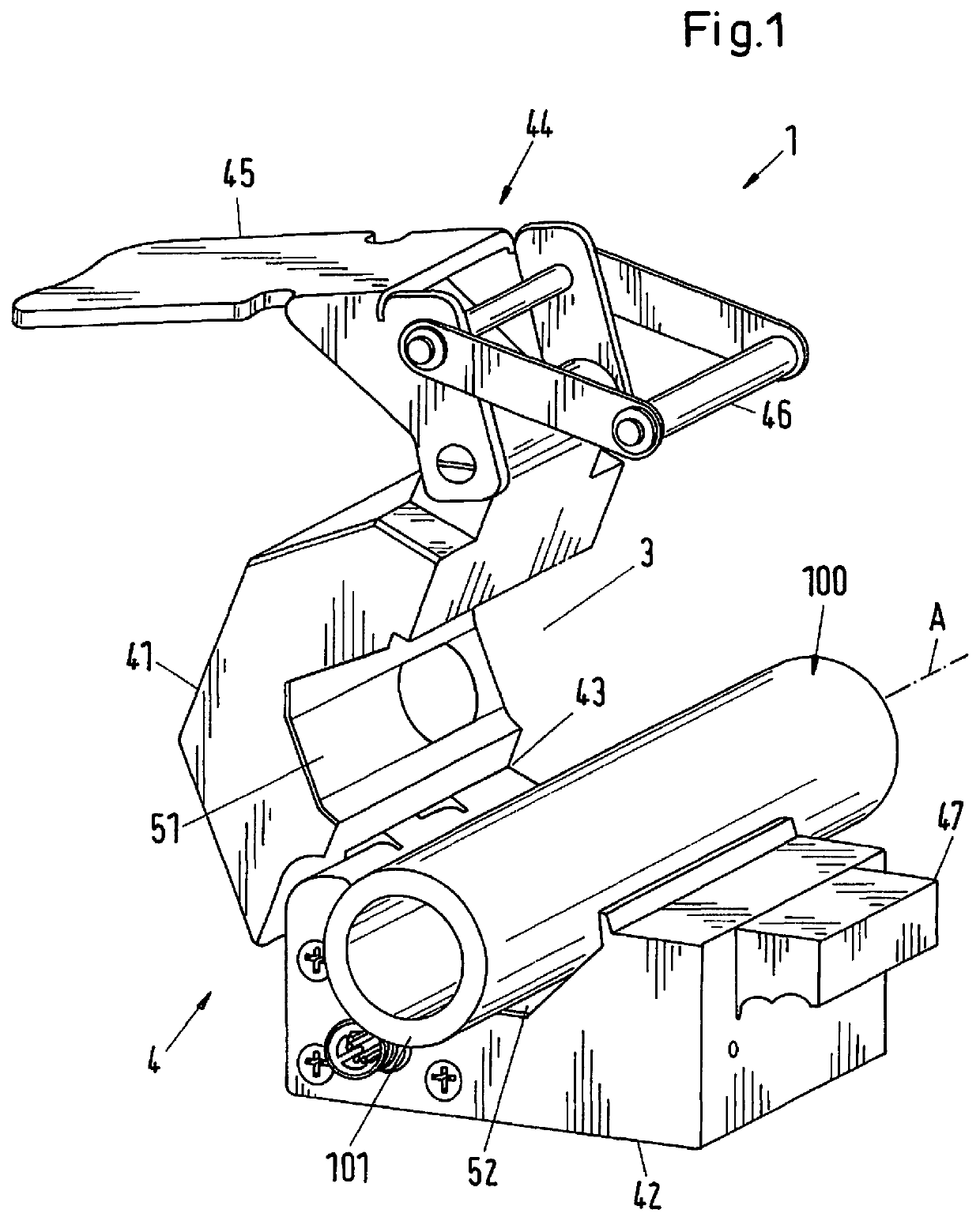
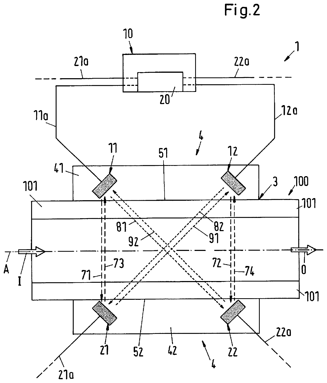
[0058]FIG. 2 shows in a schematic illustration of an ultrasonic measuring device 1 according to the invention. The housing 4 of the ultrasonic measuring device 1 can be designed in particular as explained in FIG. 1.

[0059]In this first embodiment, a total of four ultrasonic transducers 11, 12, 21, 22 are disposed in the housing 4 for the respective emitting and receiving of ultrasonic signals, namely two first ultrasonic transducers 11, 12, which are arranged laterally on the first side 51 of the central recess 3 in the closed state of the housing 4 and two second ultrasonic transducers 21 and 22, which are arranged laterally on the second side 52 of the central recess 3 in the closed state of the housing 4. Thus, the first ultrasonic transducers 11, 12 are disposed in the first housing part 41 and the second ultrasonic transducers 21, 22 in the second housing part 42, so that the central recess 3 or the pipe 100 inserted into it is arranged between the two first ultrasonic transduce...

second embodiment

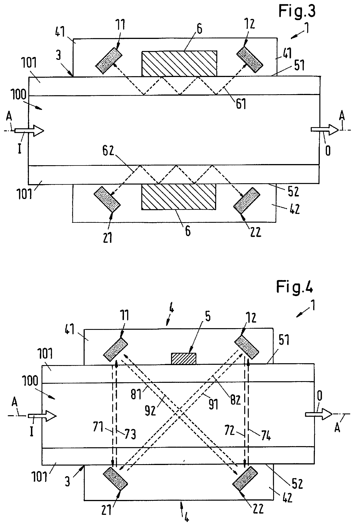
[0102]In the second embodiment, the ultrasonic measuring device 1 comprises a total of six ultrasonic transducers, namely the two first ultrasonic transducers 11, 12, the two second ultrasonic transducers 21, 22 and two calibration transducers 31, 32 for the respective emitting and receiving of ultrasonic signals.

[0103]The calibration transducers 31, 32 can be designed in the same way as the other ultrasonic transducers 11, 21, 21, 23. The term “calibration transducer” is used to distinguish between the first and the second ultrasonic transducers 11, 12 or 21, 22.

[0104]One of the two calibration transducers 31, 32 is disposed in each of the two housing parts 41, 42. In the closed state of the housing 4, the calibration transducer 31 is arranged on the first side 51 of the central recess 3 and the second calibration transducer 32 is arranged on the second side 52 of the central recess 3. Here, the two calibration transducers 31, 32 are arranged in such a way that they are opposed to ...


PUM

PropertyMeasurementUnit
frequencyaaaaaaaaaa
angleaaaaaaaaaa
temperatureaaaaaaaaaa

Abstract

An ultrasonic measuring device for measuring a fluid flowing in a pipe includes a housing and transducers. The housing receives and fixes the pipe, so that the fluid can flow through a central recess in a flow direction. The ultrasonic transducers emit and receive ultrasonic signals. Two first ultrasonic transducers are arranged laterally on a first side of the central recess, and two second ultrasonic transducers are arranged on a second side of the central recess. The second side is opposed to the first side, so that the recess is located between the first and the second ultrasonic transducers, and the ultrasonic transducers are arranged and aligned so that one of the first ultrasonic transducers emits a first measuring signal to one of the second ultrasonic transducers obliquely to the flow direction and receive a second measuring signal emitted by the second ultrasonic transducer obliquely to the flow direction.

Description

CROSS-REFERENCE TO RELATED APPLICATION[0001]This application claims priority to European Application No. 17203028.0, filed Nov. 22, 2017, the contents of which are hereby incorporated herein by reference.FIELD OF THE INVENTION[0002]The invention relates to an ultrasonic measuring device for the measurement on a fluid flowing in a pipe and to a method for the ultrasonic measurement on a fluid flowing in a pipe.BACKGROUND OF THE INVENTION[0003]Ultrasonic measuring devices for measurement of a fluid flowing in a pipe are used for example to determine the flow of the fluid through a pipe, for example a flexible plastic hose. It is a known measure to design the measuring device as a clamping device in such a way that it can be clamped onto a flexible pipe or that the pipe is clamped by the measuring device. The pipe with the fluid flowing in it is then applied with ultrasonic signals. After passing through the pipe and the fluid, the ultrasonic signals are received by an ultrasonic trans...

Claims


Application Information

Patent Timeline
Patent Type & Authority Patents(United States)
IPC IPC(8): G01F1/66G01F15/02G01N9/24G01N29/22G01N11/04G01N29/032G01N29/024
CPCG01F1/662G01F1/667G01F1/668G01F15/02G01N9/24G01N11/04G01N29/222G01N29/024G01N29/032
Inventor SCHÖB, RETOBARLETTA, NATALE
Owner LEVITRONIX
Why Eureka
Try Eureka