
Method and electronic device for controlling external electronic device

a technology of electronic devices and electronic devices, applied in the direction of user interface execution, data switching networks, instruments, etc., can solve the problems of inconvenient user operation, inconvenient user operation, and currently executing applications may be unintentionally terminated, so as to eliminate the burden of searching for and executing installed programs to control external electronic devices, the effect of simple operation

Active Publication Date: 2021-06-29
SAMSUNG ELECTRONICS CO LTD
View PDF19 Cites 21 Cited by
  • Summary
  • Abstract
  • Description
  • Claims
  • Application Information

AI Technical Summary

Benefits of technology

Simplifies the process of managing external device settings by allowing users to easily identify and change settings through a straightforward interface, reducing the burden of program installation and operation, and freeing developers from creating additional applications for communication and control.

Problems solved by technology

Conventionally, an electronic device provides only setting items related to the current state of the electronic device, whereby a user is unable to additionally register predetermined information, for example, a setting item other than the items set in the current electronic device, which is a drawback.
Conventionally, for the connection and communication between the electronic device and the external electronic device, a user may need to additionally install, in the electronic device, an installation program provided from a developer of the external electronic device or the like, which is inconvenient for the user.
Also, when an electronic device desires to change the state or settings of a connected external electronic device, the user needs to search for and execute a corresponding application installed in the electronic device, which is also inconvenient for the user.
In this instance, the currently executing application may be unintentionally terminated, which causes inconvenience for the user.

Method used


Image

  • Method and electronic device for controlling external electronic device
  • Method and electronic device for controlling external electronic device
  • Method and electronic device for controlling external electronic device

Examples


Embodiment Construction

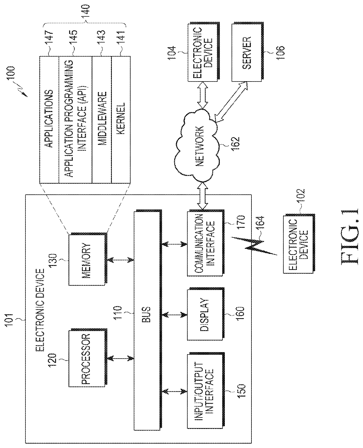
[0027]Hereinafter, various embodiments of the present disclosure will be described with reference to the accompanying drawings. However, it should be understood that there is no intent to limit the present disclosure to the particular forms disclosed herein; rather, the present disclosure should be construed to cover various modifications, equivalents, and / or alternatives of embodiments of the present disclosure. In describing the drawings, similar reference numerals may be used to designate similar constituent elements.

[0028]As used herein, the expression “have”, “may have”, “include”, or “may include” refers to the existence of a corresponding feature (e.g., numeral, function, operation, or constituent element such as component), and does not exclude one or more additional features.

[0029]In the present disclosure, the expression “A or B”, “at least one of A or / and B”, or “one or more of A or / and B” may include all possible combinations of the items listed. For example, the express...


PUM


Abstract

An example method for controlling an external electronic device of an electronic device, according to various embodiments, includes: receiving data information corresponding to at least one function of the external electronic device from an external electronic device connected to the electronic device; displaying a setting window for setting a user interface for controlling the external electronic device using the data information; selecting a control item corresponding to the at least one function included in the setting window according to user input reception; and setting and displaying the user interface corresponding to the selected control item.

Description

CROSS-REFERENCE TO RELATED APPLICATIONS[0001]This application is a continuation of U.S. application Ser. No. 16 / 074,866, filed Aug. 2, 2018, now U.S. Pat. No. 10,666,786, which is the National Phase Entry of PCT International Application No. PCT / KR2017 / 000649, which was filed on Jan. 19, 2017, and claims priority to Korea Patent Application 10-2016-0013615, which was filed on Feb. 3, 2016. The contents of these applications are incorporated herein by reference in their entireties.BACKGROUNDTechnical Field[0002]The present disclosure generally relates to a method and an electronic device for controlling an external electronic device.Description of Related Art[0003]The use of electronic devices, such as tablet PCs, smart phones, smart watches, and the like has become universalized, and technology related to the control of external electronic devices using a wireless communication function has been developed and applied to electronic devices, in addition to functions related to photos,...

Claims


Application Information

Patent Timeline
Patent Type & Authority Patents(United States)
IPC IPC(8): H04M1/72415H04M1/72469G06F9/451G06F3/0484G06F3/0488G08C17/02H04L12/28H04W4/12
CPCH04M1/72415G06F3/0488G06F3/04847G06F9/451G08C17/02H04L12/2818H04M1/72469H04W4/12G08C2201/20G08C2201/30G08C2201/51G08C2201/70G08C2201/93H04L2012/2841H04M2250/22
Inventor KIM, JIN-YOUNGPARK, SUNG-JAELEE, EUN-YOUNG
Owner SAMSUNG ELECTRONICS CO LTD
Learn More