
Slide rail assembly and operation method thereof

a technology of slide rail and assembly, which is applied in the direction of bearings, shafts and bearings, bearings, etc., can solve the problems of difficult assembly maintenance work, and achieve the effect of reducing the length of the slide rail assembly

Active Publication Date: 2021-07-13
KING SLIDE WORKS CO LTD +1
View PDF13 Cites 3 Cited by
  • Summary
  • Abstract
  • Description
  • Claims
  • Application Information

AI Technical Summary

Benefits of technology

[0004]The present invention provides a slide rail assembly whose innovative operation method allows the extended length of the slide rail assembly to be reduced.

Problems solved by technology

Sometimes, however, there may be spatial limitations (e.g., a limited space in which the slide rail assembly can be operated) that make it difficult to perform maintenance work on the assembly once the assembly reaches the extended length.

Method used


Image

  • Slide rail assembly and operation method thereof
  • Slide rail assembly and operation method thereof
  • Slide rail assembly and operation method thereof

Examples


Embodiment Construction

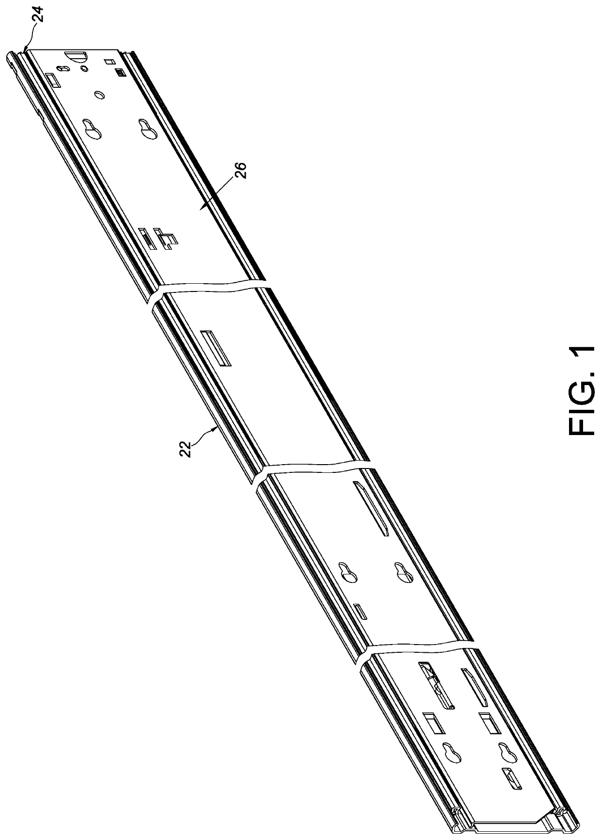
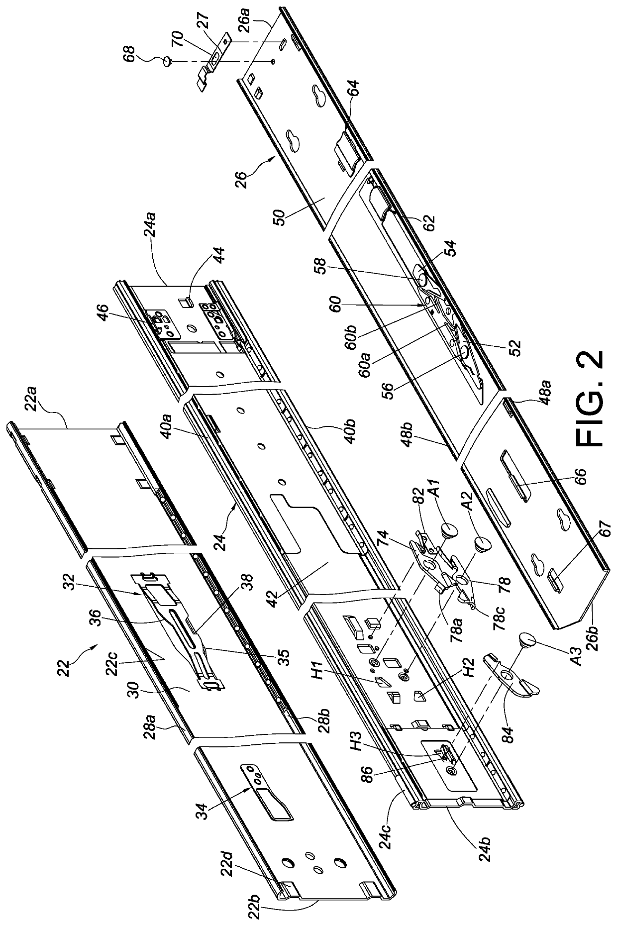
[0046]Referring to FIG. 1 and FIG. 2, the slide rail assembly according to an embodiment of the present invention includes a first rail 22, a second rail 24, a third rail 26, and a switching member 27. The slide rail assembly is shown in FIG. 1 in a retracted state.

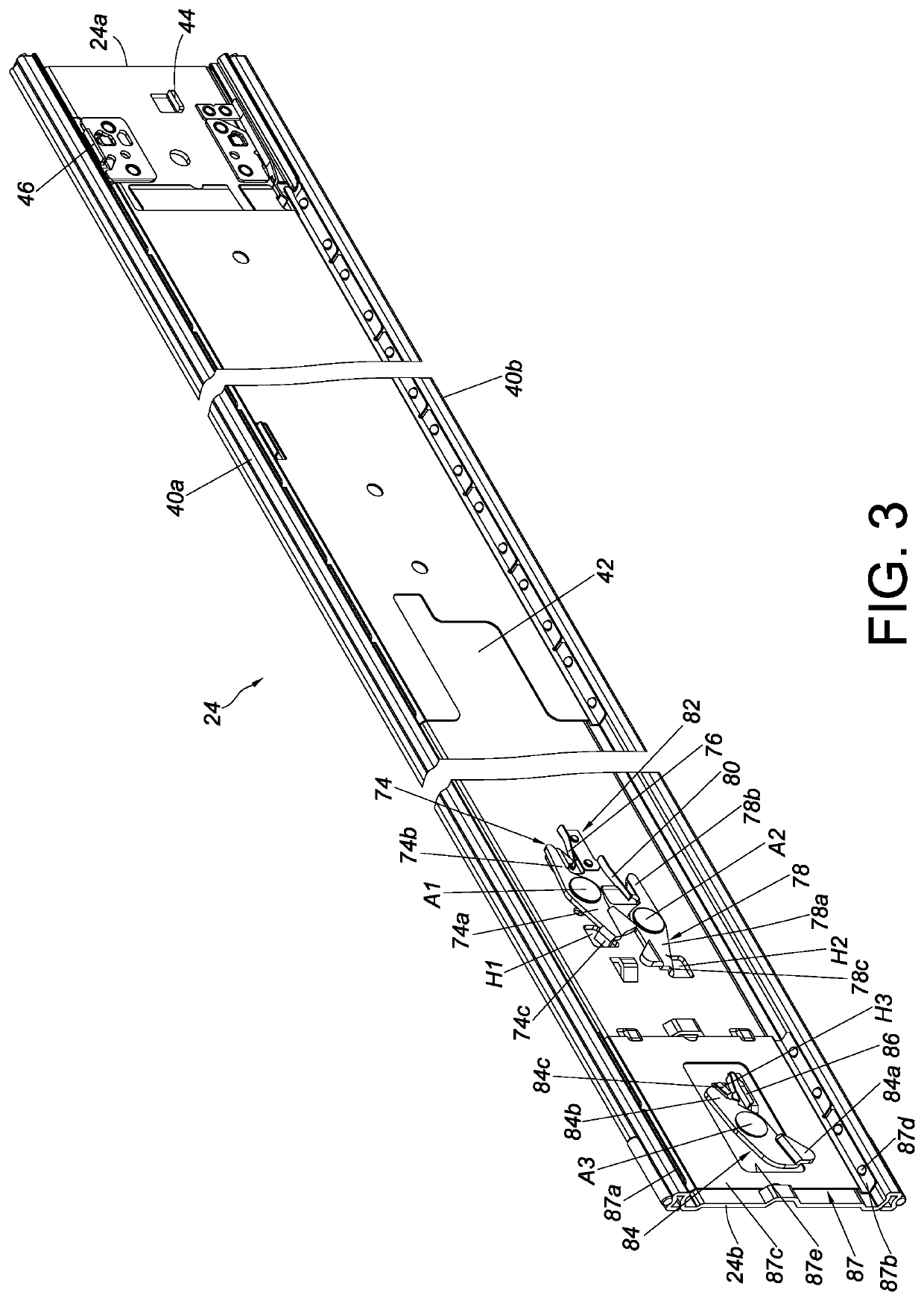
[0047]The first rail 22 has a front end portion 22a and a rear end portion 22b. The first rail 22 includes a first wall 28a, a second wall 28b, and a longitudinal wall 30 connected between the first wall 28a and the second wall 28b of the first rail 22. The first wall 28a, the second wall 28b, and the longitudinal wall 30 of the first rail 22 jointly define a first channel Preferably, the first rail 22 is provided with a first auxiliary member 32 and a second auxiliary member 34. Here, the first auxiliary member 32 is an elastic plate disposed on the longitudinal wall 30 of the first rail 22 by way of example; implementation of the first auxiliary member 32, however, is not limited by the foregoing. Preferably, the first ...


PUM


Abstract

A slide rail assembly includes a first rail, a second rail, a third rail, and a switching member. The second rail can be displaced with respect to the first rail and is provided with a working feature. The third rail can be displaced with respect to the second rail. The switching member is disposed on the third rail and is configured to contact the working feature when the third rail reaches a predetermined retracted position after being displaced from an extended position in a retracting direction, in order for the third rail to displace the second rail to a predetermined position in the retracting direction via the switching member.

Description

FIELD OF THE INVENTION[0001]The present invention relates to a slide rail assembly and more particularly to a slide rail assembly whose extended length can be reduced so that even if the slide rail assembly is used in an environment with limited space, maintenance work on the slide rail assembly can still be performed with ease.BACKGROUND OF THE INVENTION[0002]Generally, a slide rail assembly includes at least two slide rails that can be displaced with respect to each other to bring the slide rail assembly into an extended or retracted state. Take for example a three-rail slide rail assembly that includes a first rail, a second rail, and a third rail. The slide rail assembly has an extended length when in an extended state achieved by displacing the second rail and the third rail with respect to the first rail in an opening direction. Sometimes, however, there may be spatial limitations (e.g., a limited space in which the slide rail assembly can be operated) that make it difficult t...

Claims


Application Information

Patent Timeline
Patent Type & Authority Patents(United States)
IPC IPC(8): A47B88/40F16C29/04A47B88/49A47B88/493
CPCF16C29/04A47B88/49A47B88/493A47B2210/0008A47B2210/0016A47B88/44A47B2210/0072A47B2088/4235
Inventor CHEN, KEN-CHINGYANG, SHUN-HOWENG, TZU-CHENGWANG, CHUN-CHIANG
Owner KING SLIDE WORKS CO LTD
Learn More