Automatic restructuring of graphical user interface components based on user interaction

a graphical user interface and component technology, applied in the field of automatic restructuring of graphical user interface components based on user interaction, can solve the problems of unimportant client devices, unknowing exact physical location, connectivity, and negative impact on enterprise's ability to run and grow operations, and achieves small degree of manipulation or no manipulation of the gui

Active Publication Date: 2021-07-20
SERVICENOW INC
View PDF36 Cites 1 Cited by
  • Summary
  • Abstract
  • Description
  • Claims
  • Application Information

AI Technical Summary

Benefits of technology

[0002]In modern software engineering, thousands of hours are spent developing GUIs and GUI frameworks that seek to provide users with relevant information in a fashion that is easy to navigate and aesthetically pleasing. Ideally, a GUI presents a user with the desired content in a convenient location, so that a small degree of manipulation or no manipulation of the GUI (e.g., by scrolling or loading new pages) is needed in order to view this content.
[0007]As a result, users will be able to rapidly locate and manipulate the components with which they are most likely to interact. Here, an assumption is that the utilization of components in the past is reasonable predictive of future utilization of these components, which is true in many practical scenarios. By avoiding unnecessary scrolling and / or paging through components, GUI interaction time is reduced and users spend more time on the task at hand rather than seeking out components.

Problems solved by technology

It negatively impacts an enterprise's ability to run and grow its operations, innovate, and meet regulatory requirements.
The enterprise may find it difficult to integrate, streamline, and enhance its operations due to lack of a single system that unifies its subsystems and data.
The exact physical location, connectivity, and configuration of these computing devices may be unknown and / or unimportant to client devices.
To the extent that these computing tasks can be performed in parallel, such a distribution of tasks may reduce the total time to complete these tasks and return a result.
As a consequence, a security breach in this system may impact all customers' data, creating additional risk, especially for entities subject to governmental, healthcare, and / or financial regulation.
Furthermore, any database operations that impact one customer will likely impact all customers sharing that database.
Thus, if there is an outage due to hardware or software errors, this outage affects all such customers.
Likewise, if the database is to be upgraded to meet the needs of one customer, it will be unavailable to all customers during the upgrade process.
Often, such maintenance windows will be long, due to the size of the shared database.
Maintenance down time is limited because the database only contains one customer's data.
These tasks may result in proxy servers 312 logging on, or otherwise accessing information from the particular device.
Thus, if the server device is taken out of operation for maintenance, it is clear that the employee onboarding service and payroll service will be impacted.
Services might not be able to be fully determined by discovery procedures, and instead may rely on service mapping (e.g., probing configuration files and / or carrying out network traffic analysis to determine service level relationships between configuration items) and possibly some extent of manual configuration.
These GUIs are unable to adapt to the initial or changing needs of their users.
Thus, leaving the ordering as images as is can result in the GUI not providing users with easy and rapid access to information, which defeats the purpose of GUI design.
This implies that any static ordering of components is potentially problematic, as it would be unable to adapt to the changing needs of users.
As one or more users click on theses tiles, their position indicators may be updated, which may in turn cause their ordering to change.

Method used


Image

  • Automatic restructuring of graphical user interface components based on user interaction
  • Automatic restructuring of graphical user interface components based on user interaction
  • Automatic restructuring of graphical user interface components based on user interaction

Examples


Embodiment Construction

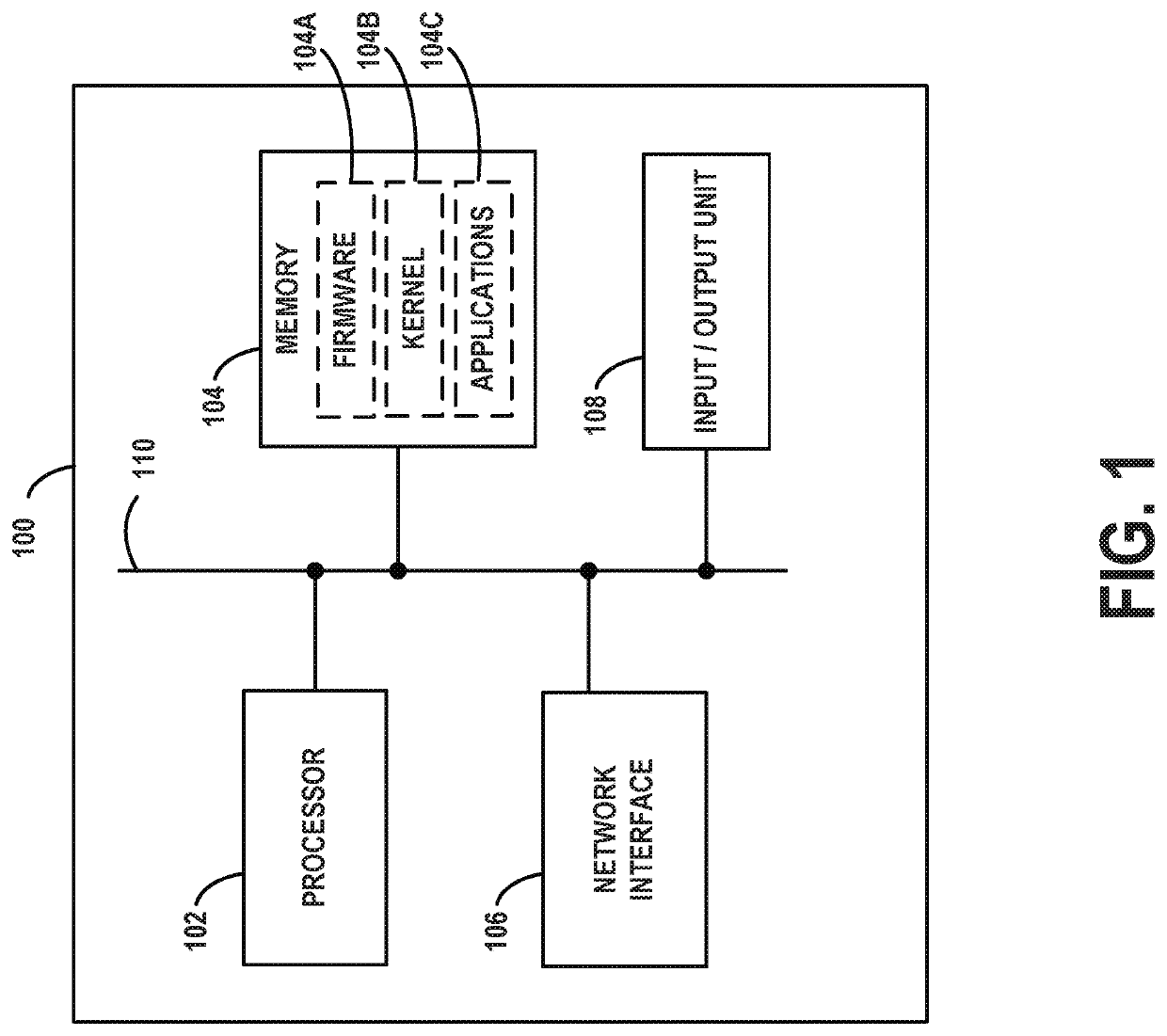
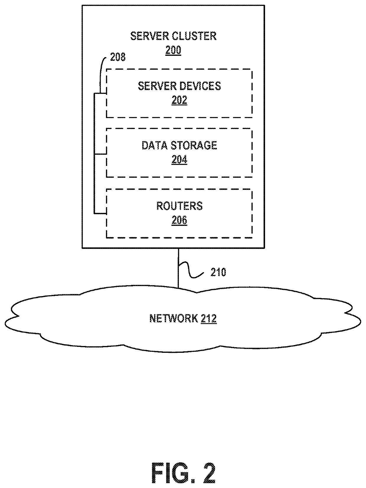
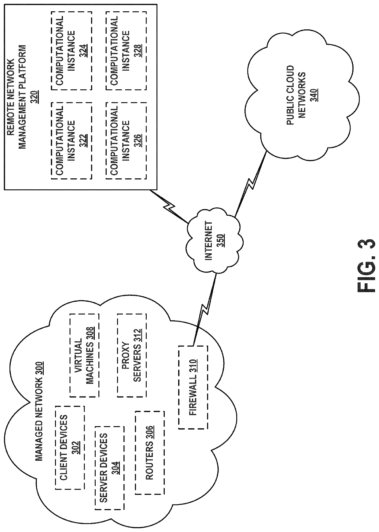
[0029]Example methods, devices, and systems are described herein. It should be understood that the words “example” and “exemplary” are used herein to mean “serving as an example, instance, or illustration.” Any embodiment or feature described herein as being an “example” or “exemplary” is not necessarily to be construed as preferred or advantageous over other embodiments or features unless stated as such. Thus, other embodiments can be utilized and other changes can be made without departing from the scope of the subject matter presented herein.

[0030]Accordingly, the example embodiments described herein are not meant to be limiting. It will be readily understood that the aspects of the present disclosure, as generally described herein, and illustrated in the figures, can be arranged, substituted, combined, separated, and designed in a wide variety of different configurations. For example, the separation of features into “client” and “server” components may occur in a number of ways....


PUM


Abstract

A memory stores a hierarchy representing an arrangement of content for a graphical user interface (GUI), wherein the content includes sibling components that have a common parent component, wherein components of the GUI are respectively associated with position indicators and click counts. One or more processors are configured to: (i) provide a first representation of the GUI with the sibling components arranged according to a first ordering, wherein the first ordering is based on the position indicators of the sibling components; (ii) receive selections of the components, wherein the selections are received by way of the GUI; (iii) update the click counts based on the selections; (iv) recalculate the position indicators based on the click counts; and (v) provide a second representation of the GUI with the sibling components arranged according to a second ordering, wherein the second ordering is based on the position indicators as recalculated.

Description

BACKGROUND[0001]Most modern computer software is accessed by way of a graphical user interface (GUI). Whether displayed on a mobile device, laptop, personal computer, or other platform, such GUIs generally include of a hierarchy of components disposed in particular arrangements. These components may be a combination of one or more containers, blocks, text boxes, buttons, selectors, widgets, tiles, panes, carousels, and so on. Each component may include text content, image content, audio content, video content, links, or some combination thereof. Traditional GUIs render components in a predefined, preconfigured, or static fashion, in that these components may be arranged to fit on a screen in a particular way and in a particular hierarchy, and the ordering of the hierarchy and the components within each level of the hierarchy does not change. As a consequence, if the default component ordering does not reflect the actual usage volume of these components, frequently used components ma...

Claims


Application Information

Patent Timeline
Patent Type & Authority Patents(United States)
IPC IPC(8): G06F3/0482H04L29/08
CPCG06F3/0482H04L67/22G06F3/0481H04L67/535
Inventor NEELISETTI, V. S. M. R. K. HAREESHDALAL, AVISHEK
Owner SERVICENOW INC
Why Eureka
Try Eureka