Apparatus and method for generating a microfoam

a microfoam and apparatus technology, applied in the field of methods and apparatus for generating microfoams, can solve the problems of increasing environmental problems, inconvenient use as disposable items, and difficult to meet the needs of users, so as to prevent the appearance of dead zones or minimize the effect of cos

Active Publication Date: 2021-08-03
TRIPLE LINE TECH LTD
View PDF43 Cites 0 Cited by
  • Summary
  • Abstract
  • Description
  • Claims
  • Application Information

AI Technical Summary

Benefits of technology

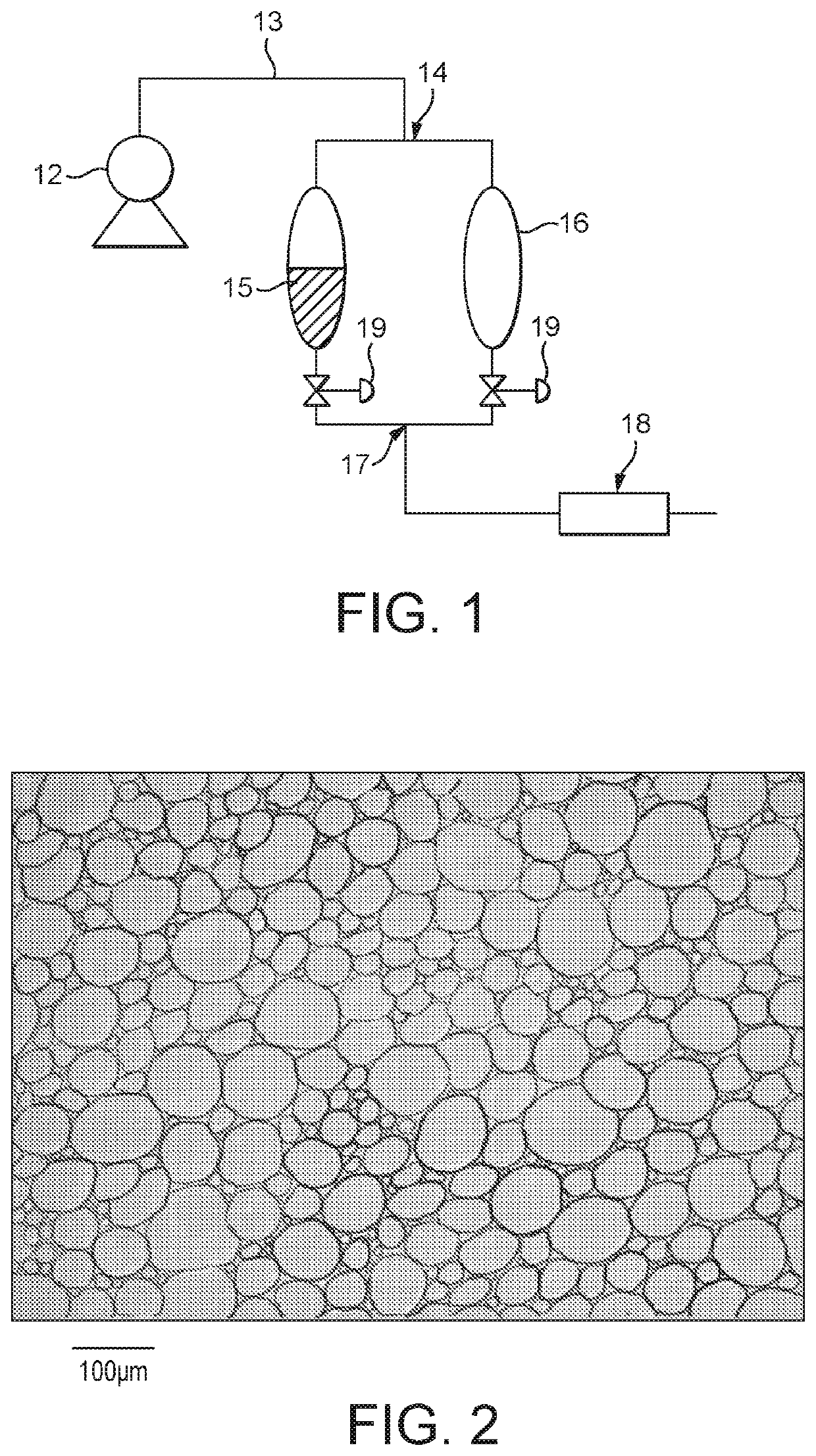
[0012]For any given microfoam a particular range of gas-to-liquid-ratio will need to be achieved. This can easily be obtained by varying the source pressures and / or the resistances of the flow channels of the gas and liquid respectively using methods known to the person skilled in the art.
[0014]Because the apparatus and method does not involve moving parts it can be made relatively cheaply and at essentially any scale. This allows it to be used on small scale dispensing applications through to industrial applications.
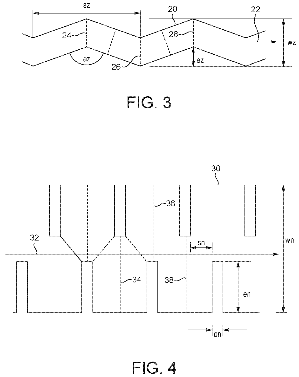
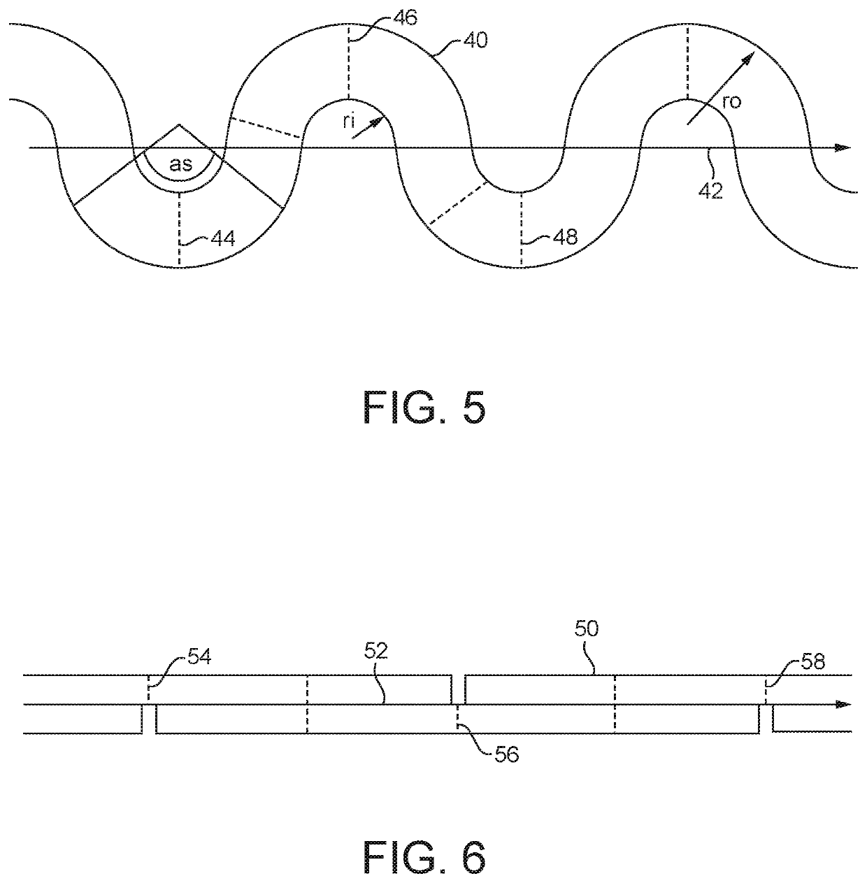
[0020]This means that the spatially oscillating flow channel is a single channel with no splits and re-merging of channels. A single oscillating channel with an inlet and outlet provides advantages over devices that do comprise junctions. For example it minimizes or prevents the appearance of dead zones.
[0021]However this single flow channel may comprise additional inlets which introduce liquid and / or gas into the single flow channel. Additionally the single flow channel may comprise additional outlets, so that some of the flow splits before leaving the apparatus via one of the outlets. However, if the flow splits in this way then the split fluids do not get re-merged together downstream and simply leave the apparatus via an exit. In this way the advantages of a single directed flow path are maintained in the apparatus, despite the possible presence of more than one inlet and outlet.
[0023]It has been found that providing the average cross sectional area of the spatially oscillating flow channel to be from 0.5 to 5 mm2 gives good results.

Problems solved by technology

Thus, known methods of generating microfoams are fairly expensive and bulky to manufacture and are not convenient for use as a disposable item, for example as part of consumer packaging.
However these are increasingly being perceived as problematic both environmentally and from a health and safety perspective.
However a packed column is inconvenient as it can create dead zones which raise hygiene issues.

Method used


Image

  • Apparatus and method for generating a microfoam
  • Apparatus and method for generating a microfoam
  • Apparatus and method for generating a microfoam

Examples


first embodiment

[0076]a rechargeable refillable aerosol in FIG. 8 comprises a retaining vessel 104, for holding a foamable fluid 101, a headspace of compressed gas 102, and a microfoaming section 105 with gas conduit 108. Additionally, there is a screw-fit cap assembly 112, 113 with seal 111, incorporating a pressurised gas charging port 115 with one-way valve 116, and a hand actuated valve-spring assembly 117, 118 and nozzle 119 for the control and dispensing of microfoam.

[0077]The aerosol device is initially filled with foamable fluid at atmospheric pressure 103. The cap assembly 112 is then applied to the retaining vessel 104 sealing the vessel contents from the external atmosphere via interlocking screw threads 113, a compressible seal 111, and closed valves 116, 117 within the flow paths of the cap. The headspace 102 of the device is pressurised to the required level via connecting the high-pressure gas connector 114 to an external charging supply of the desired gas. Charging supplies of gas m...

second embodiment

[0080]a rechargeable refillable aerosol for the generation and dispensing of microfoams is illustrated in FIG. 10. This embodiment comprises a retaining vessel 137, for holding a foamable fluid 134, a headspace of compressed gas 135, and a dip tube 154 with gas conduit 141. Additionally, there is a screw-fit cap assembly 145, 146 with seal 144, incorporating a pressurised gas charging port 148 with one-way valve 149, a hand actuated valve-spring assembly 150, 151 and nozzle 152 housing a microfoaming section 138. The microfoaming section 138 may be integral to the nozzle, but it may also be detachable to enable cleaning, replacement, or interchange with microfoaming sections of different design. The aerosol device is initially filled with foamable fluid at atmospheric pressure 136. The cap assembly 145 is then applied to the retaining vessel 137, sealing the vessel contents from the external atmosphere via interlocking screw threads 146, a compressible seal 144, and closed valves 14...


PUM

PropertyMeasurementUnit
average cross sectional areaaaaaaaaaaa
average distanceaaaaaaaaaa
mean bubble diameteraaaaaaaaaa

Abstract

An apparatus or method for generating a microfoam, the apparatus comprising a channel having an inlet and an outlet, a source of foamable liquid and pressurised gas arranged to feed into the inlet, wherein the channel is comprised of a spatially oscillating flow channel to provide an oscillating flow direction, the spatially oscillating flow channel oscillating about a bulk flow direction, the spatially oscillating flow channel providing a sequence of planar cross-sections perpendicular to the flow direction, with a sub-sequence of planar cross-sections that are perpendicular to the bulk flow direction in the plane in question, the sub-sequence comprising at least one plane that does not overlap with at least one other plane in the sub-sequence.

Description

TECHNICAL FIELD[0001]The present invention relates to a method and apparatus for generating a microfoam utilising a channel having an inlet and an outlet.BACKGROUND AND PRIOR ART[0002]Foams are two phase systems which consist of a continuous liquid or solid phase that surrounds discrete gas entities. The continuous phase of a foam typically contains a surfactant or stabiliser which prevents the bubbles from coalescing and hence hinders the bubbles from reverting back to a continuous gas phase and separating out of the foam. Microfoams can be defined as a special case of foams wherein the bubbles are typically smaller than 100 microns and have a low polydispersity (e.g. a standard deviation of less than 40 microns).[0003]Methods and apparatuses for generating microfoams are known.[0004]Mechanical whipping relies on the use of mechanical moving parts to use mechanical shear to reduce the bubble size, for example in a high shear mixer. Such mixers rely on rotation of a high-speed impel...

Claims


Application Information

Patent Timeline
Patent Type & Authority Patents(United States)
IPC IPC(8): B01F3/04B05B15/531B05B15/55B01F5/06B01F13/00B05B7/00B05B7/04B65D83/42B33Y80/00
CPCB01F3/04446B01F5/065B01F5/0606B01F5/0647B01F13/0022B05B7/0025B05B7/0483B05B15/531B05B15/55B65D83/42B01F2215/0014B33Y80/00B01F23/235B01F25/4231B01F25/4333B01F25/4331B01F33/50111B01F2101/06B01F25/31112B65D83/14B01F23/20
Inventor NICMANIS, MARKGOTHARD, MICHELLE
Owner TRIPLE LINE TECH LTD
Why Eureka
Try Eureka