Shift control device and shift control method for vehicle

a technology of shift control and shift control, which is applied in the direction of mechanical equipment, transportation and packaging, and driver input parameters, can solve the problems of not being able to improve fuel economy, and achieve the effect of improving fuel economy, reducing the rotation speed of the engine, and enlarge the traveling scen

Active Publication Date: 2021-08-03
JATCO LTD +1
View PDF6 Cites 0 Cited by
  • Summary
  • Abstract
  • Description
  • Claims
  • Application Information

AI Technical Summary

Benefits of technology

[0006]It is, therefore, an object of the present invention to provide a shift control device for a vehicle which is devised to solve the above-described problems, and to enlarge a traveling scene in which a fuel cut for an improvement of a fuel economy is performed, when an accelerator pedal is released during a traveling.
[0010]In this way, the minimum rotation speed of the engine is increased, regardless of the vehicle front condition and the accelerator operation condition. With this, it is possible to enlarge the traveling scene in which the fuel cut control for improving the fuel economy is performed, when the accelerator pedal is released during the traveling.

Problems solved by technology

However, in the above-described conventional art, the release of the accelerator pedal is often not presumed before the release operation, though the accelerator pedal is released during the traveling.
Consequently, the fuel cut control is not performed, so that it is not possible to improve the fuel economy.

Method used


Image

  • Shift control device and shift control method for vehicle
  • Shift control device and shift control method for vehicle
  • Shift control device and shift control method for vehicle

Examples


first embodiment

[0020]Firstly, a configuration is explained.

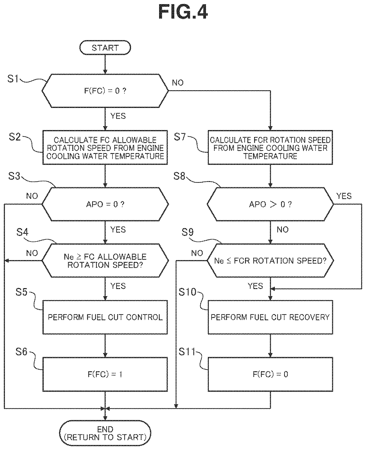
[0021]A shift control device according to the first embodiment is applied to an engine vehicle including a driving system including an engine in which a fuel cut control is performed when an accelerator release condition and an engine speed condition are satisfied, and a belt type continuously variable transmission (a torque converter+a variator). Hereinafter, the configuration in the first embodiment is explained with reference to “Overall System Configuration”, “Normal Shift Control Configuration and Lockup Control Configuration”, “Fuel Cut Control Process Configuration”, and “Shift Control Process Configuration”

[0022][Overall System Configuration]

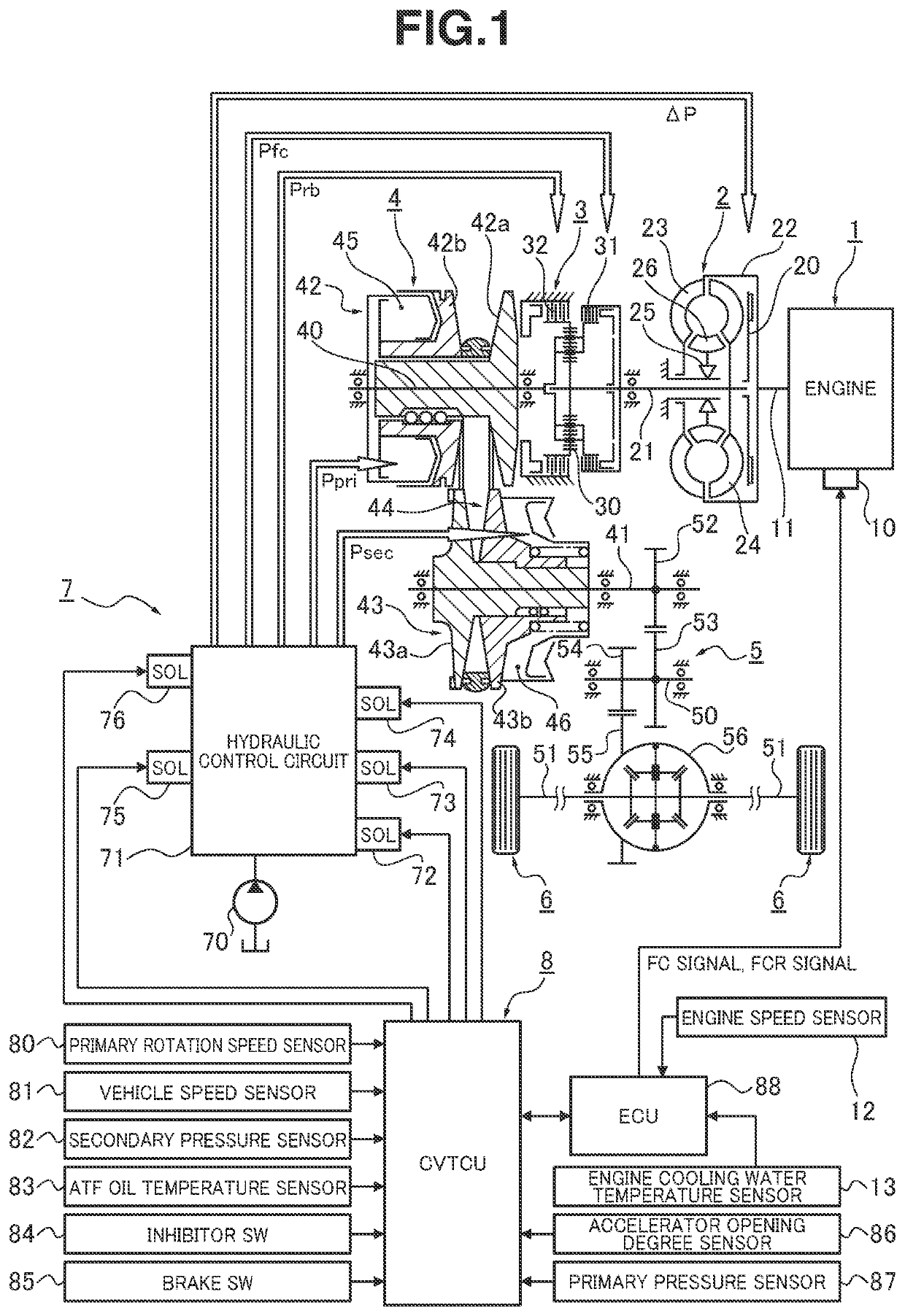
[0023]FIG. 1 shows a driving system and a control system of an engine vehicle to which the shift control device according to the first embodiment is applied. Hereinafter, the overall system configuration is explained with reference to FIG. 1.

[0024]The driving system of the engine vehicle includ...


PUM


Abstract

A shift control device for a vehicle includes: an engine; a shift mechanism disposed between the engine and driving wheels; a shift control section configured to control a transmission gear ratio of the shift mechanism; and a fuel cut control section configured to stop a fuel supply to the engine, at least when an accelerator pedal is in a release state, and when an engine speed is equal to or greater than a predetermined rotation speed, the shift control section being configured to perform a minimum rotation speed restriction control to control the transmission gear ratio of the shift mechanism so that the minimum rotation speed of the engine is equal to or greater than the predetermined rotation speed regardless of a vehicle front condition and an accelerator operation condition.

Description

TECHNICAL FIELD[0001]This invention relates to a shift control device for a vehicle including an engine, the shift control device configured to perform a fuel cut control by using an accelerator operation condition and an engine speed condition.BACKGROUND ART[0002]Conventionally, in a case where a release of an accelerator pedal is presumed in accordance with a traveling condition of a preceding vehicle ahead of own vehicle, a transmission gear ratio of an automatic transmission is controlled so that an engine speed becomes equal to or greater than a predetermined rotation speed before the accelerator pedal is released. With this, it is possible to perform a fuel cut control when the accelerator pedal is released, and to improve a fuel economy. Besides, the release of the accelerator pedal is presumed based on a descending road ahead of the vehicle, and decrease of an intervehicle distance between the own vehicle and the preceding vehicle (cf. for example, patent document 1).[0003]H...

Claims


Application Information

Patent Timeline
Patent Type & Authority Patents(United States)
IPC IPC(8): B60W30/18B60W10/06B60W10/107F16H59/22F16H59/36F16H59/74F16H59/78B60W30/188F16H61/66F16H61/662
CPCB60W30/18072B60W10/06B60W10/107F16H59/22F16H59/36F16H59/74F16H59/78B60W30/1884B60W2510/0647B60W2510/0676B60W2540/10B60W2710/06B60W2710/0655B60W2710/1005B60W2720/00F16H61/66F16H61/662F16H2059/366F16H2059/746B60Y2300/46F16H59/42F16H61/0204F16H61/14F16H61/66259F16H2059/186F16H2061/0232F16H59/24F16H61/02
Inventor ARAKI, TOSHIMITSUHONMA, TOMOAKIENDO, YASUHIROKUROIWA, HIROSHI
Owner JATCO LTD
Why Eureka
Try Eureka