
Low-NOx-burner

a low-no, burner technology, applied in the field of burners, can solve the problems of limited thermal nox production, and achieve the effect of enhancing the recirculation of flue gas and enhancing the utilization of remaining burnable reactants

Active Publication Date: 2021-08-17
MESSER IND USA INC
View PDF37 Cites 1 Cited by
  • Summary
  • Abstract
  • Description
  • Claims
  • Application Information

AI Technical Summary

Benefits of technology

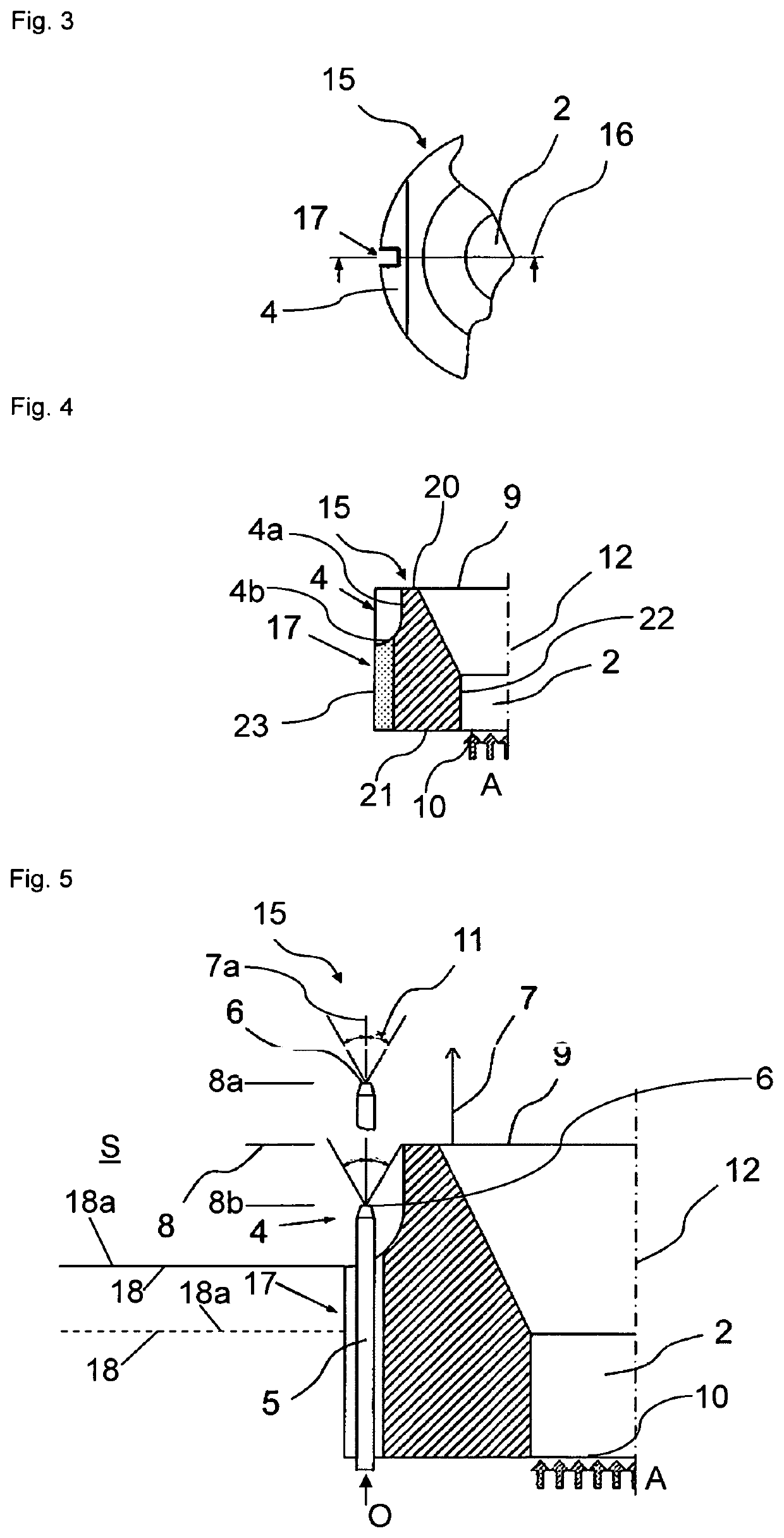
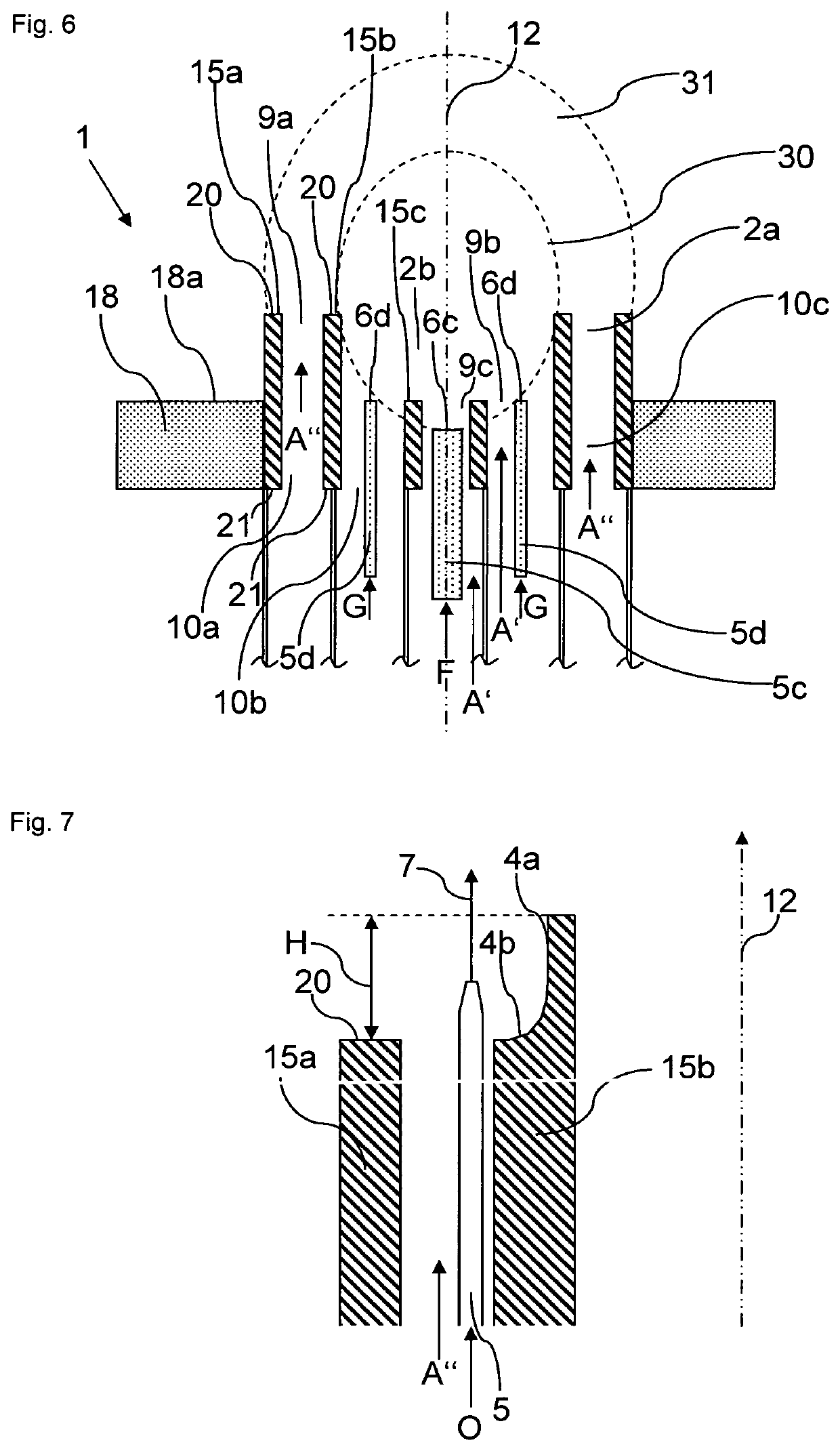
[0014]Advantageously, the at least one oxygen lance allows for ejecting oxygen adjacent to the generated flame so as to allow for an enhancing of the recirculation of the flue gas back into the flame, which flue gas is generated by the combustion of the fuel with the oxygen in the primary air. Here, according to the invention, the flue gas recirculation is particularly enhanced due to the fact that the ejection of oxygen according to the invention generates an underpressure adjacent the at least one oxygen lance which causes flue gases in the fire box / ambience of the burner to recirculate into the flame of the burner which reduces the NOx, content in the flue gas due to the fact that the inert flue gas cools the flame and also reduces the partial pressure of oxygen O.
[0026]Advantageously, the (e.g. concave) bottom surface and the lateral surface of the second recess allow flue gases to recirculate along these surfaces back into the flame generated by the burner which reduces the total NOx content in the flue gas due to the fact that the inert flue gas cools the flame and reduces the partial pressure of oxygen thus lowering thermal NOx emissions. Due to said recirculation a diluted steam of oxygen is generated that gets in touch with the fuel. In case there would be no separation between the two streams, the oxygen would “attract” the fuel and then create a hotter zone where NOx would be generated.
[0029]Thus, particularly, the tile provides a shield designed for screening an air supply provided through said air inlet from an oxygen supply provided through the ejection nozzle of the oxygen lance, so that oxygen ejected by the nozzle of the oxygen lance is at first ejected into a colder flue gas region surrounding the relatively hotter flame and not directly into the flame. This recirculates colder flue gas into the relative hot region of the flame, but the momentum is generated by an oxygen stream. The effect is then double: the colder flue gas lowers the peak flame temperature “spreading” the flame on a wider region, the oxygen content improves the combustion conditions and stabilises the flame.
[0033]According to an embodiment of the staged fuel burner, the oxygen lances are configured to generate an oxygen swirl of the ejected oxygen, wherein particularly the oxygen swirl has the same direction as the air swirl or an opposite direction (see also above). Particularly, in this respect, swirling the oxygen in the same direction as the air can be beneficial to the flame stability; against it can increase turbulence, e.g. the mixing effect, so that burning of the fuel is enhanced. Particularly, this can be an advantage with fuels that can produce PAH (precursors of the PM10 and PM2,5) or sensible amount of CO.
[0047]The Low-NOx-burner according to this invention particularly provides an enhanced flue gas recirculation and enhanced exploitation of remaining burnable reactants within the flue gas, wherein the tile is implementable into a conventional burner configuration.

Problems solved by technology

Thus, the thermal NOx production is limited by reducing the flame temperature.
Finally, prompt NOx usually only produces a small amount of the generated NOx, which however may be a significant portion of the total NOx when a low-NOx-burner is employed that reduces the total NOx.

Method used


Image

  • Low-NO<sub>x</sub>-burner
  • Low-NO<sub>x</sub>-burner
  • Low-NO<sub>x</sub>-burner

Examples


Embodiment Construction

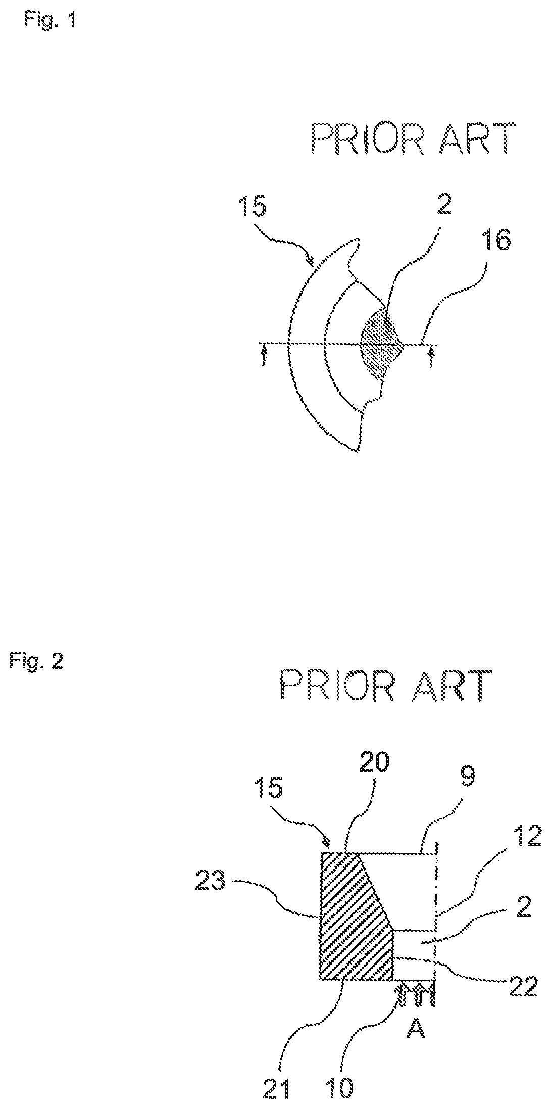
[0057]FIG. 1 shows a conventional burner tile 15 out of a refractory material such as Alumina based refractory having a central air inlet 10.

[0058]In FIG. 2 a cross sectional view along plane 16 of FIG. 1 of the conventional burner tile 15 is shown. The air inlet 2 is in flow connection to a central opening 2 of the tile 15, which opening 2 extends along a burner axis 12 and ends at a discharge outlet 9 for discharging a flame generated by the burner.

[0059]In detail, the tile 15 further comprises a front side 20 and a rear side 21 that faces away from the front side 20 of the tile 15, wherein the rear side 21 delimits said air inlet 10, and wherein the front side 20 delimits said discharge outlet 9. The air inlet 10 is in flow connection to an air source for feeding air into said opening 2 of the tile 15 that is needed for combustion of fuel. The tile 15 further comprises an inside 22 facing said central opening 2 as well as an outside 23 facing away from said opening 2.

[0060]FIGS. ...


PUM


Abstract

A burner is provided which includes a tile surrounding an opening of the tile extending along a burner axis, the tile including a front side and a rear side, wherein the rear side has an air inlet connected to the opening for feeding air into the opening, and the front side has a discharge outlet connected to the opening for discharging a flame into a surrounding area. The burner includes at least one oxygen lance extending along the burner axis in a first recess of the tile, and the oxygen lance having an ejection nozzle at an end region of the lance for ejecting oxygen, wherein the at least one oxygen lance is mounted with the ejection nozzle positioned along the burner axis to be adjustable between an uppermost position and a lowermost position via a zero-position in between the uppermost position and the lowermost position.

Description

CROSS-REFERENCE TO RELATED APPLICATIONS[0001]This application claims priority under 35 USC § 119 to International Patent Application No. PCT / EP2015 / 001657 filed on Aug. 11, 2015 which claims priority from European Patent Application EP 14003024.8 filed on Sep. 2, 2014.BACKGROUND OF THE INVENTION[0002]The invention relates to a burner for generating a flame by combustion of a fuel, comprising: a tile surrounding an opening of the tile extending along a burner axis, the tile further comprising a front side and a rear side facing away from the front side, wherein the rear side comprises an air inlet connected to said opening for feeding air into said opening, and wherein said front side comprises a discharge outlet connected to said opening for discharging a flame generated by the burner into a surrounding area, and wherein the tile further comprises an inside facing said opening as well as an outside facing away from said opening the burner further comprising at least one oxygen lance...

Claims


Application Information

Patent Timeline
Patent Type & Authority Patents(United States)
IPC IPC(8): F23C6/04F23L7/00F23D14/22
CPCF23C6/045F23D14/22F23L7/007F23C2201/301F23L2900/07005Y02E20/34
Inventor SCHREINER, BERNHARDRANGMARK, LENNARTEKMAN, TOMASGUSBERTI, AMBROGIO
Owner MESSER IND USA INC
Learn More