Engine intake and exhaust device with variable cycle intake and exhaust gas recirculation

A technology of exhaust gas recirculation volume and intake air volume, which is used in exhaust gas recirculation, engine components, engine control, etc. requirements, air intake and exhaust gas recirculation restrictions, etc., to achieve the effects of low vibration and noise, small pressure fluctuations, and improved economy and emissions

Active Publication Date: 2018-01-05
ZHENGZHOU UNIVERSITY OF AERONAUTICS
View PDF7 Cites 0 Cited by
  • Summary
  • Abstract
  • Description
  • Claims
  • Application Information

AI Technical Summary

Problems solved by technology

The problem in the air intake and exhaust device of the above-mentioned naturally aspirated engine is that the air volume entering the engine cylinder and the recirculated exhaust gas volume in each cycle are affected by the end pressure of the intake air in the cylinder, because the structure of the traditional intake and exhaust system cannot Therefore, the intake air volume and exhaust gas recirculation volume entering the cylinder in each cycle are limited, the maximum intake air volume cannot be adjusted flexibly, and the exhaust gas recirculation rate can only be adjusted within a small range, which cannot be adjusted according to the working conditions of the engine. Carry out self-adaptive optimal regulation, so it cannot meet the requirements of intake air supply and exhaust gas recirculation in various complex working conditions of the engine, and cannot achieve the effect of engine power optimization and nitrogen oxide emission optimization
[0004] But this invention is only designed for the adaptive adjustment of the exhaust pipe volume of the exhaust system, and does not involve the intake adjustment, so the air entering the engine cylinder every cycle The exhaust gas volume and recirculation exhaust gas volume are still limited; and when adjusting the volume of the exhaust pipe, the moving plate and elastic parts are limited by the length of the exhaust pipe, and the moving displacement is very limited. Larger tube volume requirements

Method used


Image

  • Engine intake and exhaust device with variable cycle intake and exhaust gas recirculation

Examples


Embodiment

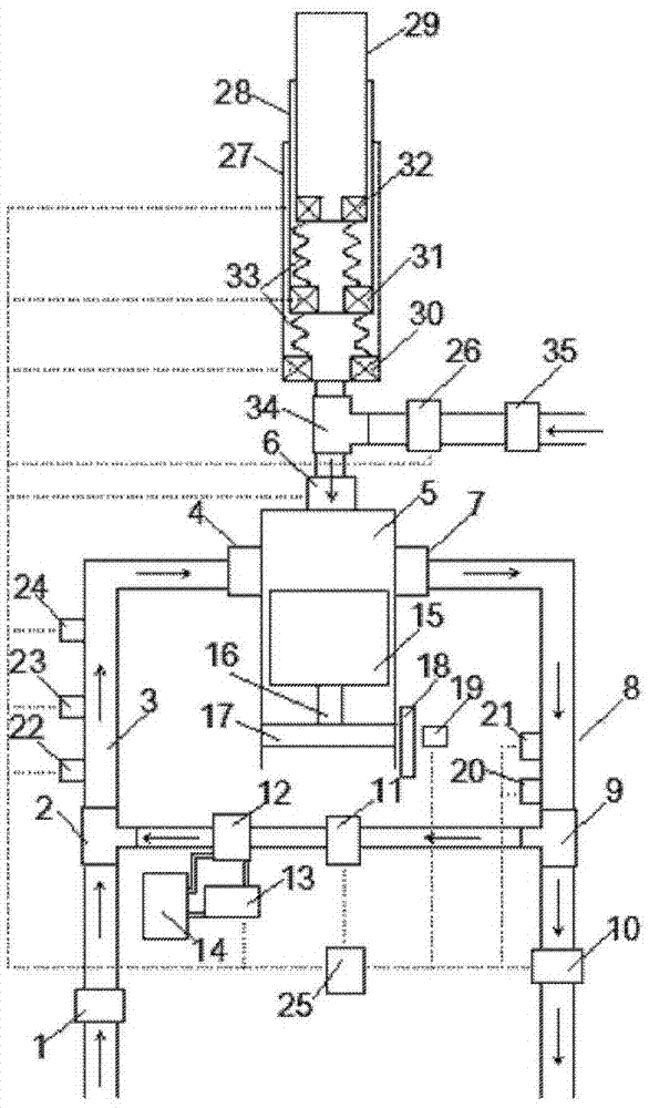
[0018] Example: see figure 1 , in the figure, 1-air filter A, 2-tee joint A, 3-intake pipe, 4-intake valve, 5-engine cylinder, 6-auxiliary intake and exhaust port, 7-exhaust valve, 8 -exhaust pipe, 9-tee joint B, 10-exhaust back pressure valve, 11-exhaust gas recirculation valve, 12-exhaust gas cooler, 13-electric water pump, 14-water tank, 15-piston, 16-connecting rod , 17- crankshaft, 18- flywheel, 19- crankshaft position sensor, 20- exhaust pressure sensor, 21- exhaust temperature sensor, 22- intake pressure sensor, 23- intake air temperature sensor, 24- carbon dioxide sensor, 25- Controller, 26-control valve, 27-telescopic cylinder, 28-primary piston, 29-secondary piston, 30-fixed electromagnet, 31-first-level electromagnet, 32-secondary electromagnet, 33-return spring, 34-Tee joint C, 35-air filter B. The arrow in the figure shows the gas flow direction, and the dotted line is the control circuit.

[0019] The air filter A1 is connected with an inlet of the three-way j...


PUM


Abstract

The invention discloses an engine intake and exhaust device with variable circulating air inflow and exhaust gas recirculation volume. The engine intake and exhaust device comprises an intake pipe and an exhaust pipe, wherein the intake pipe and the exhaust pipe are communicated with an inner cavity of an engine cylinder respectively through an intake valve and an exhaust valve; the inner cavity of the engine cylinder is communicated with an inner cavity of a cylinder body of a telescopic cylinder through an auxiliary intake and exhaust valve and a communicating pipe; electromagnets are arranged in the inner cavity of the cylinder body of the telescopic cylinder; besides, return springs are arranged between the cylinder body and a piston of the telescopic cylinder; an auxiliary intake pipe is arranged on the communicating pipe; a control valve is arranged on the auxiliary intake pipe; the exhaust pipe and the intake pipe are communicated through a cut-through pipe; and an exhaust gas recirculation valve and an exhaust gas cooler are arranged on the cut-through pipe. According to the engine intake and exhaust device, the air inflow of air entering the engine cylinder in each circle can be remarkably increased, the intake density of the engine is increased, the energy is saved, the working efficiency is improved, and the dynamic property, economy and emission property of the engine are improved.

Description

Technical field: [0001] The invention relates to an engine intake and exhaust device for a naturally aspirated engine used in a vehicle, in particular to an engine intake and exhaust device with variable cycle intake volume and exhaust gas recirculation volume. Background technique: [0002] The energy crisis and environmental pollution are becoming more and more serious. Vehicle engines are facing severe fuel shortage and emission control problems. It is urgent to improve the economic performance and emission performance of the engine. The performance of the engine depends largely on its intake and exchange process, that is, the engine discharges the exhaust gas that has been burned in this cycle and inhales the fresh air or combustible mixture in the next cycle. In order to improve the power and economy of the engine, it is necessary to increase the amount of air entering the engine cylinder per cycle. At the same time, in order to control the harmful emissions of nitroge...

Claims


Application Information

Patent Timeline
Patent Type & Authority Patents(China)
IPC IPC(8): F02B33/02F02B33/30F02M26/13F02M26/30F02D21/08
CPCF02B33/02F02B33/30F02D41/0055F02D2021/083
Inventor 侯军兴刘建伟文振华魏永强孙新刘元朋李启璘尹欣冯宪章蒋志强
Owner ZHENGZHOU UNIVERSITY OF AERONAUTICS
Why Eureka
Try Eureka