Method and device for treating filament yarn with air

a technology of air treatment and filament yarn, which is applied in the direction of beaming machines, manufacturing tools, transportation and packaging, etc., can solve the problems of excessively large discrepancy between spinning rate and performance, natural limit of performance dictated, and surging, so as to increase air speed, increase production cost, and increase pressure

Inactive Publication Date: 2002-03-12
HEBERLEIN MASCHFAB +1
View PDF13 Cites 4 Cited by
  • Summary
  • Abstract
  • Description
  • Claims
  • Application Information

AI Technical Summary

Benefits of technology

The inventor has also discovered that an upper meaningful limit for the air pressure actually existed with the former practice involving the air treatment of yarn by means of air treatment nozzles. In the first instance, a natural upper pressure limit of about 12 bar is noticed with pressure generators or compressors if compression is carried out in one stage. Secondly, all former known tests, including U.S. Pat. No. 3,279,164, showed that an increase beyond a pressure value over the range of 8 to 12 bar did not improve but rather impaired the result, depending on the concrete application. Therefore, it was not worth increasing the pressure over two or more stages, for example beyond 12 to 14 bar. To this was added the logic that, in each case, the increase in the air pressure cannot be used to increase the air speed despite the much higher production costs. The inventor accordingly adopted the reverse procedure. He recognized early that, in many applications, it was not the air speed alone or the increase in the air speed which must be decisive but rather a combination between this and the increase in the density of the air. The inventor was surprisingly able to discover, from large numbers of tests (contrary to the former notion) beginning from 100 bar with a steady reduction to the known values, noteworthy working windows which offered ideal conditions, in particular for the false twist texturing of yarns. The determined working windows are relatively narrow, in particular at low yarn velocities, and differ with respect to different yarn qualities. In the range of fine yarns, the window was frequently between 20 and 35 bar. This pressure can easily be produced with a two- or three-stage compressor. A further surprise resided in the fact that the good results were attained almost more easily at yarn velocities above 500 m / min and up to 800 m / min. This is therefore a velocity range which allows direct "inline use", for example with known warp stretching devices. A further important point resided in the discovery that the air forces must be controllable to a much higher extent than in the state of the art. The inventor sought possible ways of achieving very high air twist intensities down to the lowest yarn ducts. A correspondingly high mass flow of air was produced with high speeds of rotation of the yarn in order to achieve this. It was noted that the twist is more intensive if the quantity of air is conveyed tangentially into the yarn duct via many small transverse ducts. However, to obtain a high mass throughput of air with small cross section transverse ducts, the pressures were tested to values within the specified range of 20 to 100 bar at the nozzle inlet. Tests have confirmed the correctness of the assumptions. High pressure which is produced in two or more stages, in particular above 20 bar, can be used economically with a miniaturized nozzle. In particular with a special geometry, as will be explained hereinafter. The improvement resides in the fact that the compressed air consumption can be markedly reduced with the same output.

Problems solved by technology

There is an excessively large discrepancy between spinning rate (POY yarn 3-4000 m / min) and the possible texturing rate in the second case.
However, there is a natural limit to performance dictated mainly by the looping, the maximum permitted tensile stress on the yarn and the frictional resistance relative to the twist discs.
If the performance of the twist discs which is to be transmitted exceeds a permitted level, surging occurs.
This effect is ultimately noticed as a defect on the finished textiles owing to periodically repeated differences, for example in colour.
The most obvious drawback of the mechanical friction spindle resides in the width dimension.
The speed of passage of the yarn which is extremely low by today's standards was probably the main reason why this air false twisting method could not succeed in practice.

Method used


Image

  • Method and device for treating filament yarn with air
  • Method and device for treating filament yarn with air
  • Method and device for treating filament yarn with air

Examples


Embodiment Construction

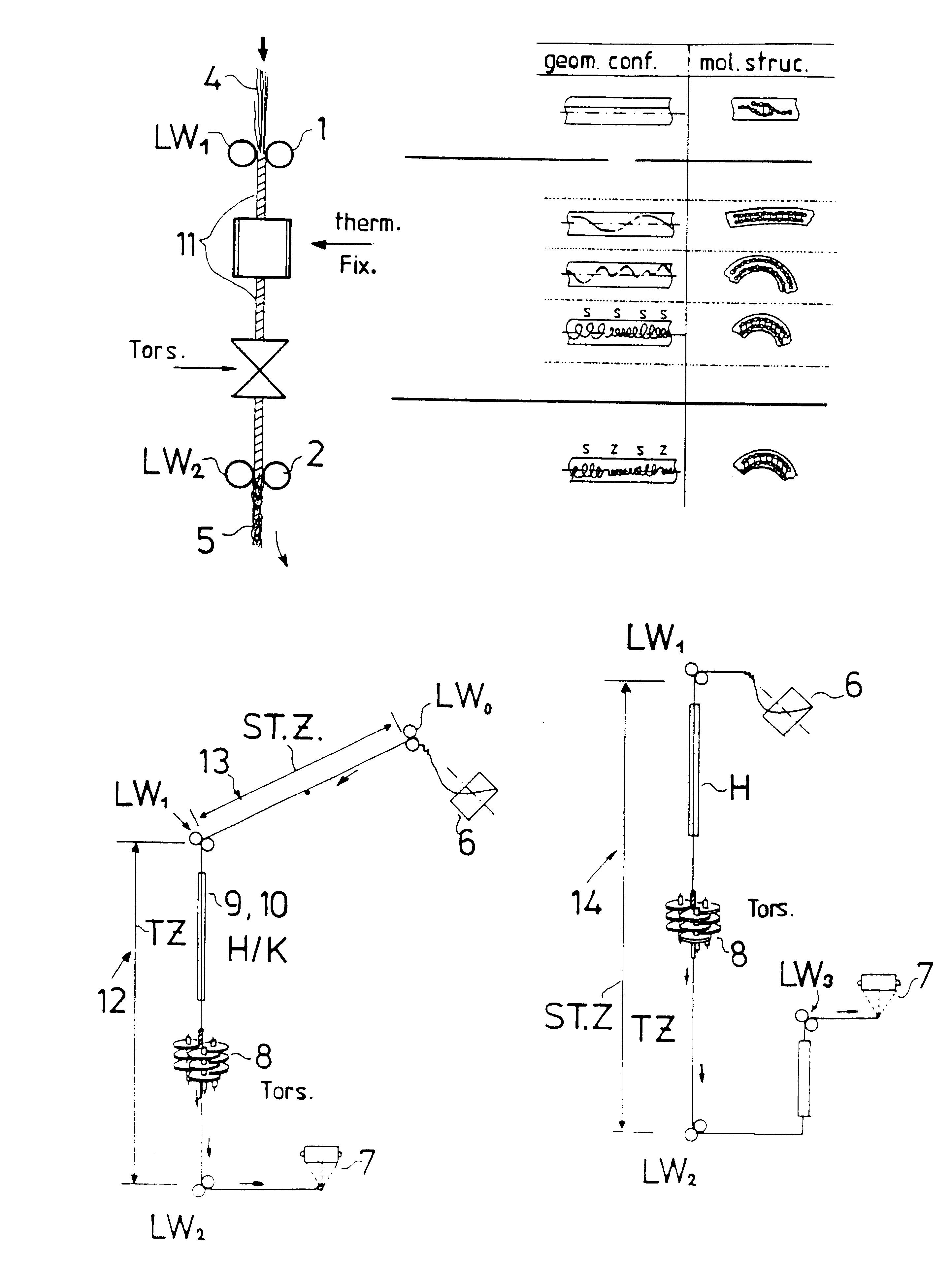
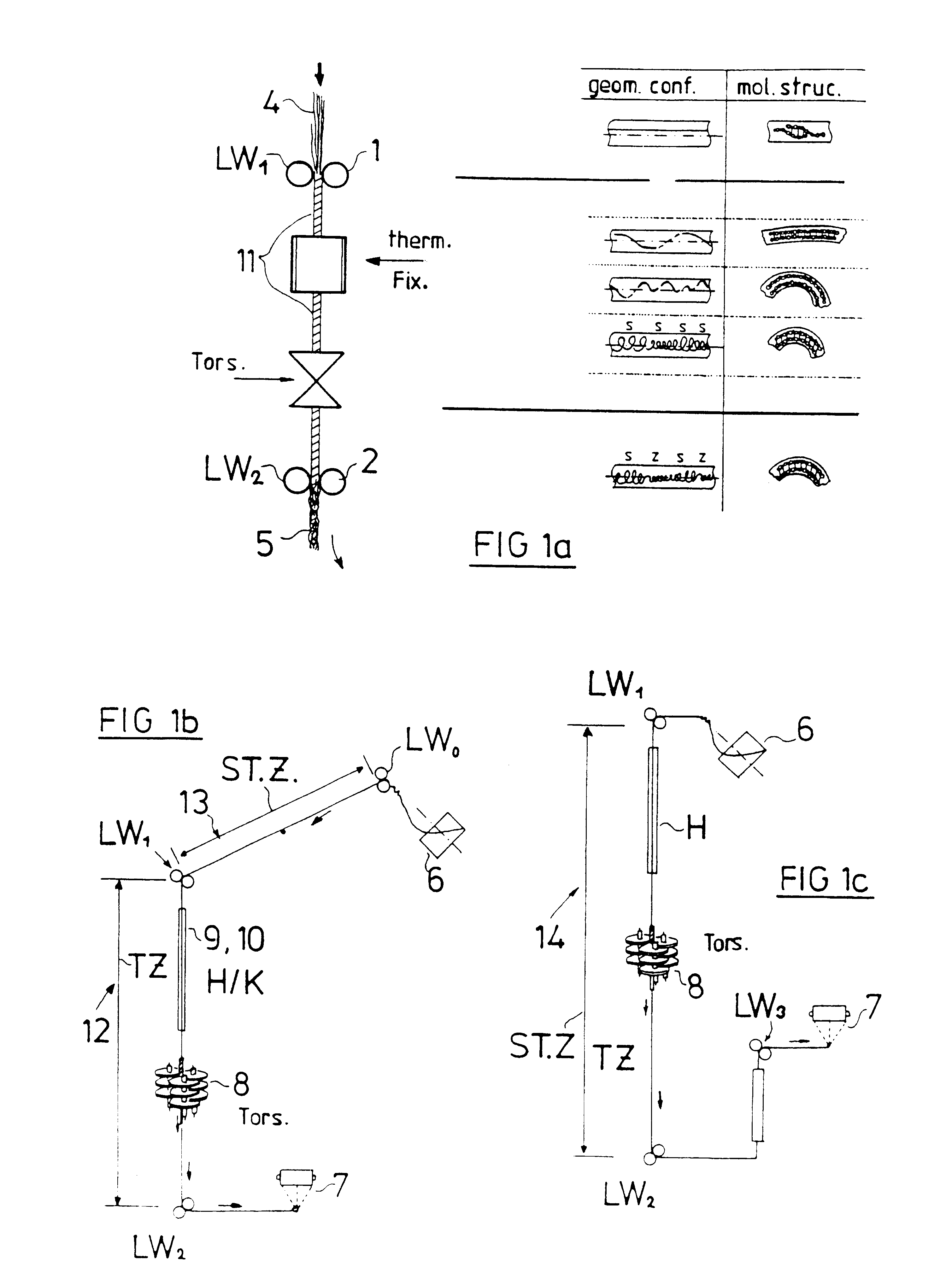
Reference will be made hereinafter to FIGS. 1a, 1b and 1c which show the current practice and the state of the art. The two basic process steps are emphasized in the left-hand half of FIG. 1a. These are torsion production (Tors) and heat setting. Smooth yarn 4 is supplied to the process via a feed unit 1 (LW1) and is taken off as crimp quality yarn 5 after the feed unit 2 (LW2). The smooth yarn 4 is taken from a supply bobbin 6 according to FIGS. 1b and 1c and rewound, for example onto a winding bobbin 7. A mechanical twister, for example a friction spindle 8, is used as twister. The heat setting means 3 (therm. Fix) consists essentially of a heater 9 (H) and a cooler 10 (K). The twister 8 acts throughout heat setting stage. The effect is shown symbolically as twisted yarn 11. However, as this is a false twist, it is removed again after the twister 8. The change in molecular orientation produced by the treatment is shown on the right of FIG. 1, on the one hand as an external geometr...


PUM

PropertyMeasurementUnit
pressureaaaaaaaaaa
pressureaaaaaaaaaa
pressureaaaaaaaaaa

Abstract

The new invention proposes that filament yarns, in particular partially stretched yarns known as POY yarns, be subjected to stretch texturing via an air treatment nozzle. The air treatment nozzles are designed in miniaturized form, have a continuous yarn duct in which there open a plurality of transverse bores for the supply of high pressure air in the range over 14 bar, preferably within specific working windows between 20 and 50 bar. With the new invention, it was possible for the first time to process POY yarn via simultaneous stretch texturing using an air twister. The invention allows an individual thread as well as a parallel bundle of threads to be treated and permits for the first time the construction of a false twist stretch texturing bundle device with simultaneous air treatment of 500 to 1000 and more threads.

Description

The invention relates to a method and an apparatus for the air treatment of filament yarn with yarn treatment nozzles having a continuous miniaturized yarn duct into which compressed air or gaseous fluid is introduced and a dominant twisting flow is produced in the yarn duct.STATE OF THE ARTThe production of yarn from synthetic fibres involves quite a number of basic stages. The individual continuous filaments are extruded via spinnerets from hot liquid thermoplastic polymer raw material and are then solidified in a cooling stage. A desired number of filaments are then combined to form a single thread or yarn which is either cut into staple fibre or left as a continuous filament. The staple product will not be described in detail hereinafter. It is subjected to processing steps similar to those whose basic principle is known from conventional natural yarn production. The very fine filament produced under high pressure as well as the yarn produced therefrom has a number of basic prop...

Claims


Application Information

Patent Timeline
Patent Type & Authority Patents(United States)
IPC IPC(8): D02J1/08D02J1/00D02G1/12D02G1/16D02G1/02D01H1/00D01H1/115D02G1/20D02G1/04
CPCD01H1/115D02G1/02D02G1/0206D02J1/08D02G1/161D02G1/20D02G1/122
Inventor SIMMEN, CHRISTIAN
Owner HEBERLEIN MASCHFAB
Why Eureka
Try Eureka