Optical fiber cutting device

a cutting device and optical fiber technology, applied in the direction of metal-working equipment, thin material processing, metal-working equipment, etc., can solve the problems of high production cost of the blade b>150/b>, nicks of the cutting edge, and production cost increase, so as to achieve accurate positioning and increase the number of positioning sites of the cutting edge.

Inactive Publication Date: 2006-09-14
THE FUJIKURA CABLE WORKS LTD
View PDF1 Cites 44 Cited by
  • Summary
  • Abstract
  • Description
  • Claims
  • Application Information

AI Technical Summary

Benefits of technology

[0018] The invention has been made in view of the above problems. According to the invention, an optical fiber cutting device is provided where the number of positioning sites of the cutt

Problems solved by technology

However, there have been the following problems in the related art optical fiber cutting device 110 discussed above.
However, if the number of the positioning holes 151 is increased, the intervals between the holes become narrower, the strength decreases, and manufacturing thereof comes more difficult, resulting in the higher production cost

Method used


Image

  • Optical fiber cutting device
  • Optical fiber cutting device
  • Optical fiber cutting device

Examples


Embodiment Construction

[0033] Exemplary embodiments of the invention will now be described below by reference to the attached Figures. The described exemplary embodiments are intended to assist the understanding of the invention, and are not intended to limit the scope of the invention in any way. Like reference numerals refer to like elements throughout.

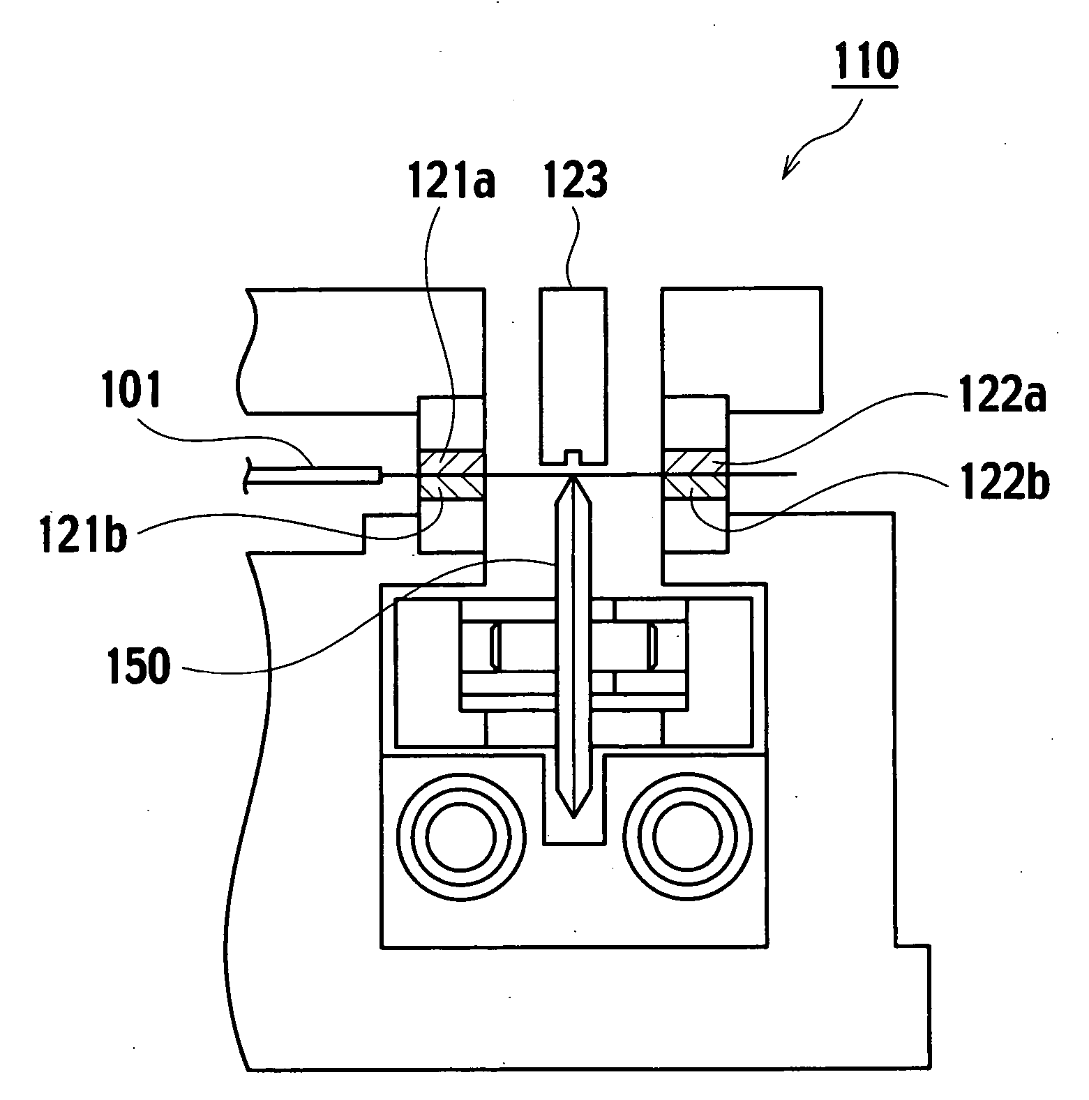
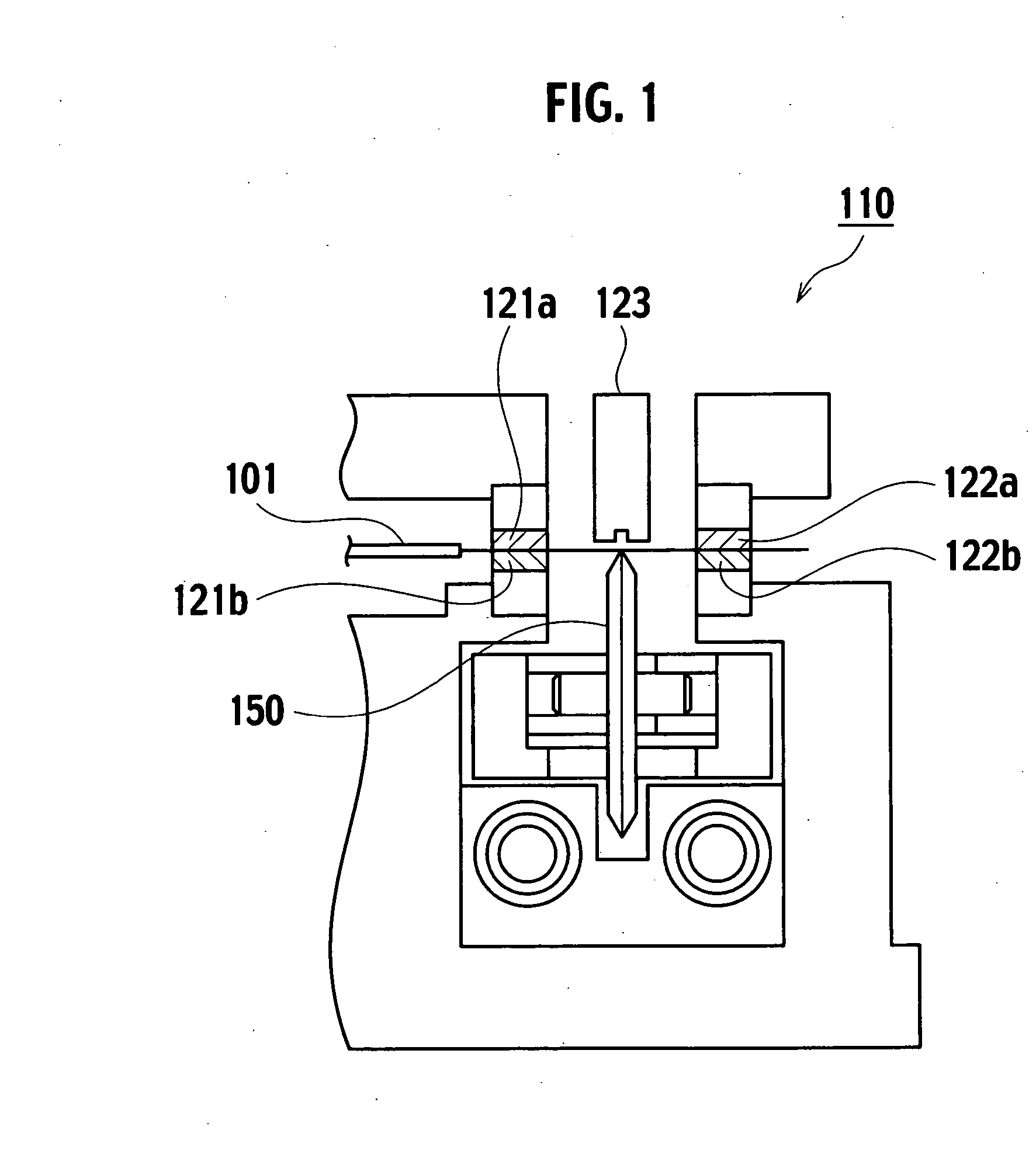
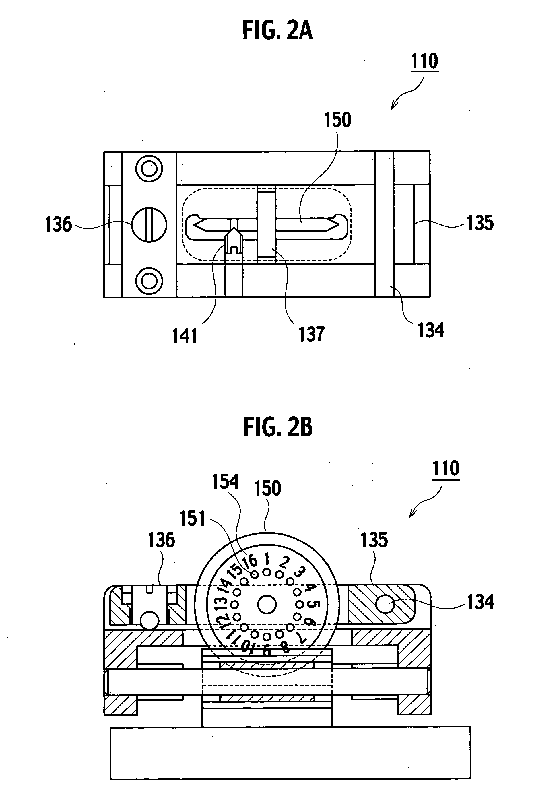
[0034]FIG. 6 is a front view showing an exemplary embodiment of an optical fiber cutting device according to the invention, and FIG. 7A is a plan view and FIG. 7B is a side view thereof.

[0035] The optical fiber cutting device 10 holds horizontally an optical fiber 1 with a pair of upper and lower clamps 21 (21a, 21b), 22 (22a, 22b) disposed on the left side and the right side of a base 20. A blade 50 is disposed between the clamps 21, 22, and is moved substantially perpendicularly to the principal axis of the optical fiber 1 to make a cut in a surface of the optical fiber 1 by a cutting edge 70. The optical fiber is cut off by applying stress to the cut...


PUM


Abstract

An optical fiber cutting device including: a rotatable blade including positioning holes; a first fastening member that is engageable with said positioning holes; and a second fastening member that is engageable with said positioning holes. When said first fastening member is engaged with a first one of said positioning holes, said second fastening member is not engaged with any of said positioning holes. Thus, the blade is fixed in a non-rotating state after being rotated by a predetermined angle.

Description

CROSS-REFERENCE TO RELATED APPLICATIONS [0001] This application is based upon and claims the benefit of priority under 35 U.S.C. §119(a) from Japanese Patent Application No. 2005-063953, filed on Mar. 8, 2005, in the Japanese Patent Office, the disclosure of which is incorporated herein in its entirety by reference. BACKGROUND OF THE INVENTION [0002] 1. Field of the Invention [0003] Devices, systems, and methods consistent with the invention relate to optical fiber cutting. [0004] 2. Description of the Related Art [0005] In the related art, an optical fiber cutting device has been proposed wherein a disk-like blade having a cutting edge at a circumference thereof is rotatably mounted so as to utilize an unused portion of the cutting edge by rotating over a used portion of the cutting edge, when the used portion of the cutting edge has been worn down. This results in a longer lifetime of the cutting edge. In this device, the optical fibers are cut off while keeping the cutting edge f...

Claims


Application Information

Patent Timeline
IPC IPC(8): B26F3/00
CPCB26D1/14B26D3/08B26D5/02B26D7/01B26D7/2635G02B6/25Y10T225/386
Inventor SASAKI, KATSUMIOTANI, TAKUHORINO, SEIJI
Owner THE FUJIKURA CABLE WORKS LTD
Why Eureka
Try Eureka