Valve with operating means between two outlet passages

a valve and outlet passage technology, applied in the field of valves, can solve the problems of increasing difficult cooling, and limiting the risk of the transporting fluid circulating, so as to improve the recirculation of exhaust gases, increase the cost of the valve, and limit the space requirement

Inactive Publication Date: 2011-08-11
VALEO SYST DE CONTROLE MOTEUR
View PDF1 Cites 0 Cited by
  • Summary
  • Abstract
  • Description
  • Claims
  • Application Information

AI Technical Summary

Benefits of technology

[0007]To improve the recirculation of the exhaust gases, thought has been given to connecting a recirculation device to the low pressure portion of the exhaust manifold, that is to say downstream of the exhaust gas expansion zone, in order to direct the majority of the exhaust gases toward the internal combustion engine inlet circuit. It is therefore necessary to provide a valve on the low pressure portion of the exhaust manifold making it possible to direct the exhaust gases either toward the outside or toward the recirculation device. However, in this portion of the manifold, the exhaust gases undergo depollution treatments, particularly a post-combustion, that raise their temperature.

Problems solved by technology

However, in this portion of the manifold, the exhaust gases undergo depollution treatments, particularly a post-combustion, that raise their temperature.
The valve must be arranged to withstand this temperature, which increases the cost of the valve and more particularly that of the members controlling the latter such as the actuation motor and the means of transmitting the movement from the motor to the butterfly valve.
Such a structure promotes a high temperature of the valve and makes it difficult to cool.
This also limits the risk that the transported fluid circulates between the butterfly valve and the wall.

Method used


Image

  • Valve with operating means between two outlet passages
  • Valve with operating means between two outlet passages
  • Valve with operating means between two outlet passages

Examples


Embodiment Construction

[0026]Hereinafter, embodiments of the invention will be described with reference to the drawings. In embodiments of the invention, numerous specific details are set forth in order to provide a more thorough understanding of the invention. However, it will be apparent to one of ordinary skill in the art that the invention may be practiced without these specific details. In other instances, well-known features have not been described in detail to avoid obscuring the invention.

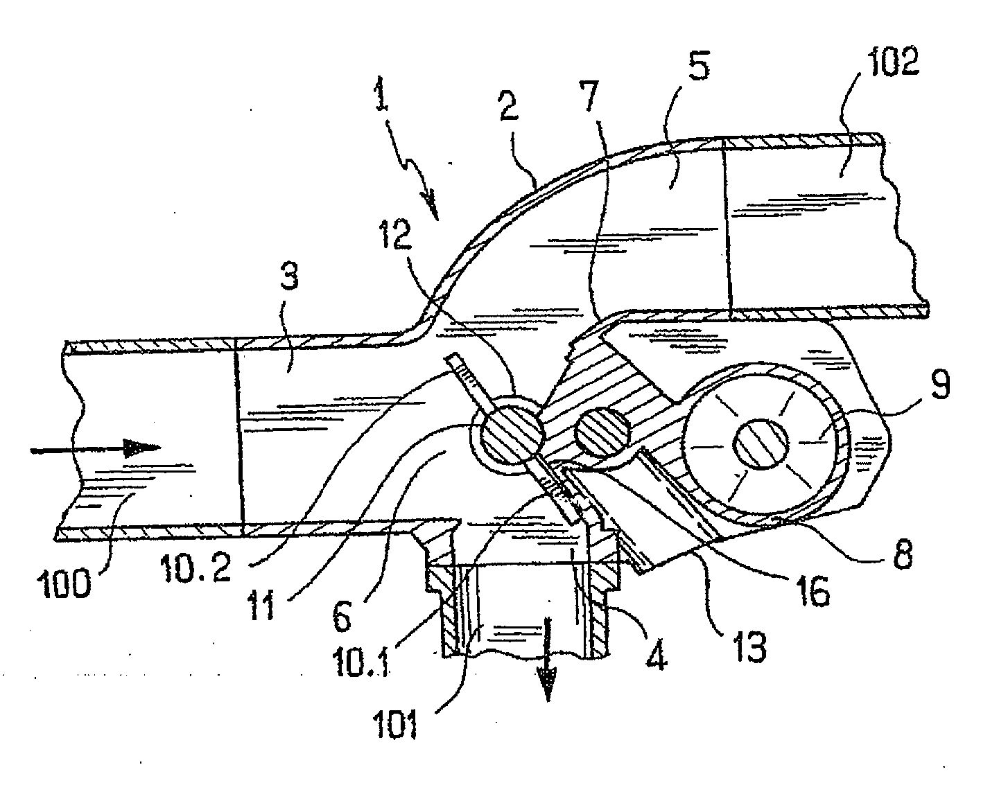
[0027]With reference to the figures, the valve generally indicated by reference number 1 is here designed to be placed on the low pressure portion of the exhaust manifold 100 of an internal combustion engine in order to direct the exhaust gases either toward the outside or toward a recirculation device 101 (only one portion of the inlet duct of the recirculation device is shown). Taking as an example an internal combustion engine fitted with a turbocharger, the low pressure portion of the exhaust manifold is down...


PUM


Abstract

A valve has a body, a fluid inlet duct and two fluid outlet ducts delimited by the body, an intersection formed at an area where the fluid inlet duct opens into the two fluid outlet ducts, and a butterfly valve disposed in the intersection. The butterfly valve is operable to be actuated between a first extreme position in which the butterfly valve directs the fluid mainly toward the first outlet duct and a second extreme position in which the butterfly valve directs the fluid mainly toward the second outlet duct. In the first extreme position, the butterfly valve has a first portion partially blocking the second outlet duct and, in the second extreme position, the butterfly valve has another portion blocking the first outlet duct.

Description

CROSS-REFERENCE TO RELATED APPLICATIONS[0001]This application is a continuation application of U.S. patent Ser. No. 12 / 091,775 filed on Apr. 28, 2008.BACKGROUND OF THE INVENTION[0002]1. Technical Field[0003]The present invention relates to a valve that can be used for example in a device for recirculating the exhaust gases of a motor vehicle internal combustion engine.[0004]2. Related Art[0005]An Exhaust Gas Recirculation device (or EGR) usually comprises a cooled channel and an uncooled channel connected on the one hand to the inlet circuit of the internal combustion engine and on the other hand to a tapping made in the high pressure zone of the exhaust manifold of the internal combustion engine. The two channels are connected to one another by a valve, called the “by-pass valve”, that regulates the flow of the exhaust gases between the cooled channel and the uncooled channel. Such a recirculation device allows a portion of the exhaust gases to be reutilized in the mixture fed into...

Claims


Application Information

Patent Timeline
Patent Type & Authority Applications(United States)
IPC IPC(8): F16K1/22F01N13/08
CPCF02M25/0709F02M25/0719F02M25/0773F02M25/0793Y02T10/121F02M25/0796F16K11/0525F16K31/041F02M25/0795F02M26/16F02M26/73F02M26/06F02M26/54F02M26/70F02M26/71Y10T137/87812Y10T137/86847Y10T137/6579F16K31/04F16K11/052
Inventor ALBERT, LAURENT
Owner VALEO SYST DE CONTROLE MOTEUR
Why Eureka
Try Eureka