Combustion chamber structure of direct injection type diesel engine

A technology for combustion chambers and diesel engines, applied to combustion engines, mechanical equipment, engine components, etc., to achieve good fuel atomization and diffusion effects

Inactive Publication Date: 2011-07-06
HINO MOTORS LTD
View PDF2 Cites 0 Cited by
  • Summary
  • Abstract
  • Description
  • Claims
  • Application Information

AI Technical Summary

Problems solved by technology

A region where fuel concentrates is formed locally, which easily leads to the generation of black smoke

Method used


Image

  • Combustion chamber structure of direct injection type diesel engine
  • Combustion chamber structure of direct injection type diesel engine
  • Combustion chamber structure of direct injection type diesel engine

Examples


Embodiment Construction

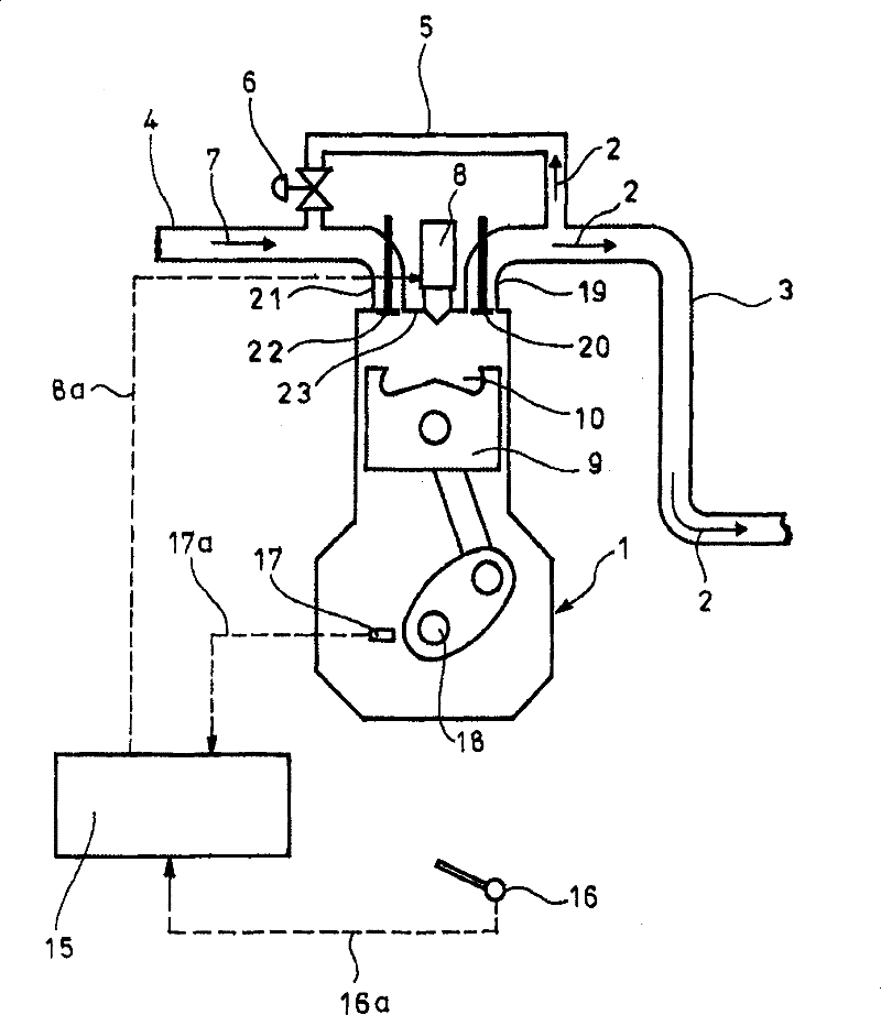
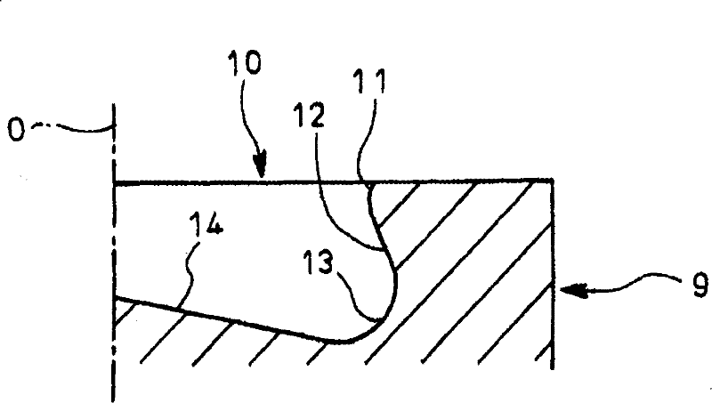
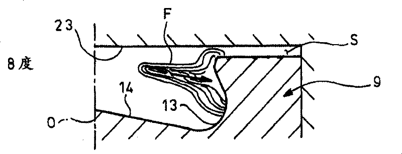
[0025] The embodiments of the present invention are explained below with reference to the drawings. Figure 13-27 Shows an embodiment of the present invention. versus figure 1 versus figure 2 The same reference numerals denote the same components.

[0026] Regarding the above reference figure 1 The illustrated direct injection diesel engine 1, in this embodiment, is as Figure 13 As shown, the outer periphery of the opening of the recess 10 that is recessed on the top surface of the piston 9 is provided with a stepped cutout 24 that is recessed relative to the top surface of the piston 9. The outer peripheral portion of the bottom surface of the cutout portion 24 rises radially outward along a gentle curved surface to form the top surface of the piston 9, and an inlet lip 11 is formed at the next step of the top surface of the piston 9, and the inlet lip 11 is formed by The inner peripheral portion of the cutout portion 24 and the combustion chamber wall portion 12 rising from ...


PUM


Abstract

Combustion chamber structure of a direct injection type diesel engine arranged such that generation of black smoke or degradation in fuel efficiency can be avoided as much as possible even if the recirculation quantity of exhaust gas is increased. In the direct injection diesel engine having a cavity (10) provided in the top surface of the piston (9) to constitute the majority of the combustion chamber and injecting fuel radially from the center of the ceiling portion of a cylinder toward the inner circumferential surface of the cavity (10) to cause it to self-ignite, a bored portion (24) recessed from the top surface of the piston (9) to form a step difference is provided in the outer circumferential part of the opening of the cavity (10). Outer circumferential part of the bottom face ofthe bored portion (24) ascends to describe a gentle curved surface toward the radial outside and reaches the top surface of the piston (9). An inlet lip (11) is formed at a position lower by one stepthan the top surface of the piston (9) by the inner circumferential portion of the bottom face of the bored portion (24) and the combustion chamber wall face portion (12) rising from the bottom face of the cavity (10).

Description

Technical field [0001] The invention relates to a combustion chamber structure of a direct injection diesel engine. Background technique [0002] Historically, some automobile diesel engines have adopted so-called exhaust gas recirculation (EGR) devices to draw part of the exhaust gas from the exhaust side back to the intake side. The exhaust gas drawn back on the intake side suppresses fuel combustion in the diesel engine. And lower the combustion temperature, thereby reducing the production of NOx. [0003] figure 1 Shows an example of a diesel engine equipped with an exhaust gas recirculation device. For the diesel engine 1 shown in the figure, the exhaust passage 3 through which the exhaust gas 2 flows and the intake passage 4 are connected by an EGR pipe 5. The EGR pipe 5 is installed in the middle The EGR valve 6 sends part of the exhaust gas 2 and intake air 7 into the cylinder of the diesel engine 1 for recirculation, so as to reduce the generation of NOx by lowering the c...

Claims


Application Information

Patent Timeline
Patent Type & Authority Patents(China)
IPC IPC(8): F02F3/26F02B23/06
CPCY02T10/125F02B23/0696F02B23/0672F02B23/0693F02B2275/40Y02T10/12F02B23/06F02F3/26
Inventor 饭洼将太郎中岛大足立祐辅下川清广
Owner HINO MOTORS LTD
Why Eureka
Try Eureka