Exhaust gas heat transfer unit

Inactive Publication Date: 2017-11-23
BENTELER AUTOMOBILTECHNIK GMBH
View PDF7 Cites 1 Cited by
  • Summary
  • Abstract
  • Description
  • Claims
  • Application Information

AI Technical Summary

Benefits of technology

[0026]The one or more guide elements prevent a backflow of exhaust gas into the heat exchanger and turbulence in the outflow diffuser. The one or more guide elements in the outflow diffuser allow the outflow diffuser to be made considerably more compact and shorter i

Problems solved by technology

This takes place in uncontrolled fashion, such that, in the bypass mode, backflows into the exhaust-gas heat exchanger can occur.
As a result, the hot exhaust gas is undesirably cooled, and the fast warm-up

Method used


Image

  • Exhaust gas heat transfer unit
  • Exhaust gas heat transfer unit
  • Exhaust gas heat transfer unit

Examples


Embodiment Construction

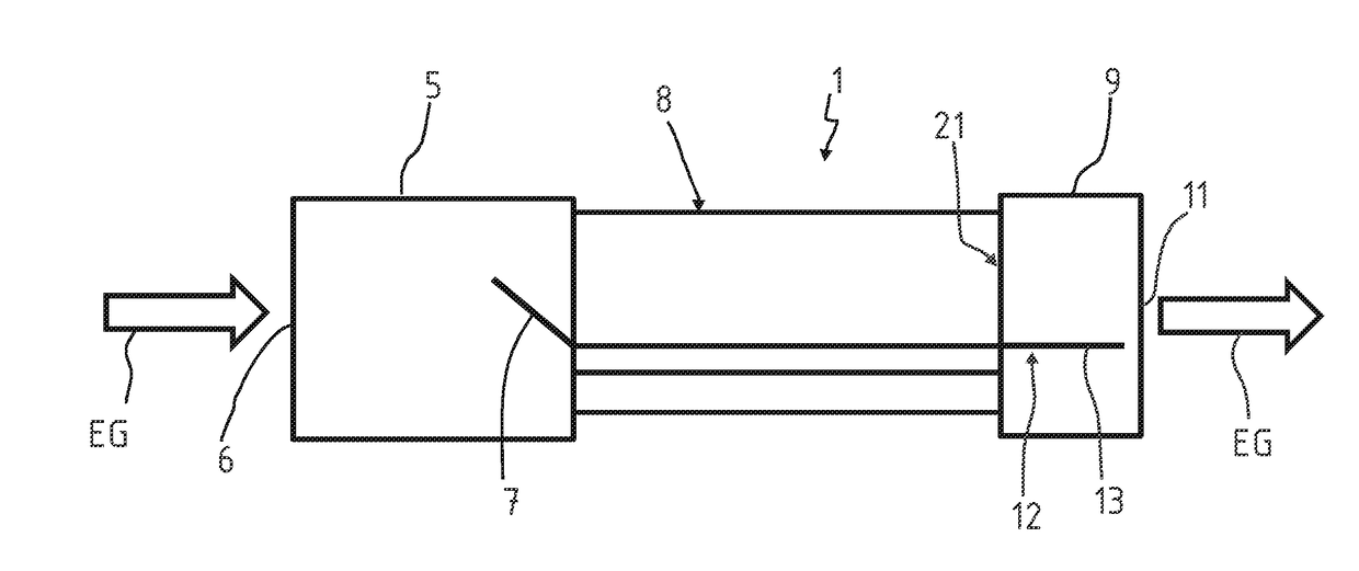
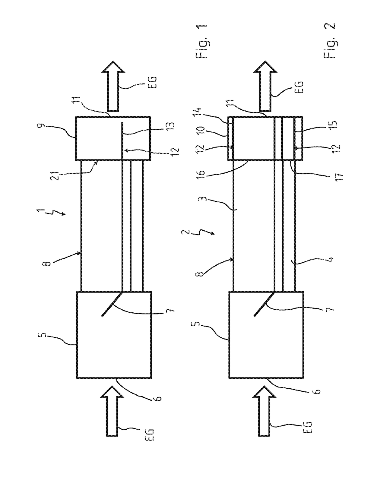
[0034]FIG. 1 illustrates an exhaust gas heat transfer unit 1 in form of a switched exhaust gas recirculation cooler (EGR cooler), and FIG. 2 illustrates an alternative embodiment of an exhaust gas heat transfer unit designated by reference numeral 2.

[0035]Each exhaust gas heat transfer unit 1, 2 includes a heat exchanger 3 functioning as an exhaust gas cooler, and a bypass duct 4. An inflow diffuser 5 is arranged upstream of the heat exchanger 3 and the bypass duct 4 in an exhaust gas flow direction shown by arrow EG in FIGS. 1 and 2. The exhaust gas EG enters the exhaust gas heat transfer unit 1, 2 via an exhaust gas inlet 6 in the inflow diffuser 5. In the inflow diffuser 5, the heat exchanger 3 and the bypass duct 4 are assigned a controller such as, but not limited to, a bypass flap 7. The bypass flap 7 functions as a switch for conducting the exhaust gas flow either through the heat exchanger 3 for cooling purposes or through the bypass duct 4 if no cooling of the exhaust gas E...


PUM


Abstract

An exhaust gas heat transfer unit is disclosed having a heat exchanger including a bypass duct, an inflow diffuser with an exhaust gas inlet, and an outflow diffuser with an exhaust gas outlet. The heat exchanger and the bypass duct are assigned a control apparatus which diverts the exhaust gas flow through the heat exchanger and/or the bypass duct.

Description

CROSS REFERENCE TO RELATED APPLICATIONS[0001]The present application claims priority to German Application Number 10 2016 109 247.9 filed May 19, 2016, the disclosure of which is hereby incorporated by reference herein in its entirety.BACKGROUND OF THE INVENTION1. Field of the Invention[0002]The present invention generally relates to an exhaust gas heat transfer unit and, more specifically, to a switched exhaust gas recirculation cooler (EGR cooler).2. Description of the Related Art[0003]Exhaust gas heat transfer units are used in motor vehicles for cooling the exhaust gases. That is, an exhaust gas cooler in the exhaust gas recirculation system (EGR) serves to reduce the exhaust gas temperature and thus reducing the nitrogen oxide and particle emissions. A part of the exhaust gas is branched off downstream of the internal combustion engine and is subsequently conducted through an exhaust gas heat transfer unit. The cooled exhaust gas is then mixed with the fresh air drawn in by the...

Claims


Application Information

Patent Timeline
IPC IPC(8): F02M26/29F01N13/08F01N5/02F01N13/18
CPCF02M26/29F01N5/02F01N2470/06F01N13/1861F01N2470/28F01N13/08F01N2240/02F02M26/26
Inventor MUELLER, SEBASTIAN
Owner BENTELER AUTOMOBILTECHNIK GMBH
Why Eureka
Try Eureka