RF communications apparatus and manufacturing method therefor

a technology of rf communication and manufacturing method, applied in the field of rf can solve the problems of inability to meet the needs of rf communication techniques, inability to optimize tracking events, and inability to accurately identify products, etc., to achieve the effect of improving rf communication apparatus and manufacturing method, low cost and small siz

Active Publication Date: 2006-09-19
NUVO HLDG
View PDF20 Cites 40 Cited by
  • Summary
  • Abstract
  • Description
  • Claims
  • Application Information

AI Technical Summary

Benefits of technology

[0021]It is an advantage of the present invention that an improved RF communications apparatus and manufacturing method are provided.
[0022]Another advantage is that an apparatus and method are provided that are compatible with a small, low cost, RF communications apparatus.
[0023]Another advantage is that an apparatus and method are provided that are compatible with low cost, low power RF communications.
[0024]Another advantage is that an apparatus and method are provided that are compatible with maximizing RF radio range at low cost and while meeting regulatory requirements.
[0025]Another advantage is that an RF communications apparatus and method are provided that are compatible with the use of a non-replaceable battery.
[0026]At least a portion of these and / or other advantages are realized in one form by a radio-frequency (RF) communications apparatus that includes a planar dielectric substrate. An RF circuit is mounted on the planar dielectric substrate. A conductive loop is formed as a first conductive trace on the planar dielectric substrate. The conductive loop has a feed point coupled to the RF circuit by a second conductive trace on the planar dielectric substrate. A tuning capacitor is formed as first and second juxtaposed conductive pads located on opposing sides of the planar dielectric substrate. The first conductive pad is in contact with a first portion of the conductive loop and the second conductive pad is in contact with a second portion of the conductive loop. The tuning capacitor and the conductive loop together form a loop antenna. The tuning capacitor has a hole that exhibits size selected to tune the loop antenna.

Problems solved by technology

Frequently, assets are misidentified, misplaced or incorrectly dispensed, thereby leading to incorrect inventory and / or receivables.
These systems, while excellent for product identification, are not optimized for tracking events that may occur to the products.
But conventional RF communication techniques fail to address the needs of systems that rely upon asset tags, and conventional RF communication techniques are not well suited to other types of RF communications apparatuses as well.
But each of these options is undesirable.
A more expensive battery, a larger battery, or a larger number of batteries poses a cost problem.
Accordingly, these are undesirable solutions when a heightened need exists for low cost.
Again, these are undesirable solutions when a need exists for making an RF apparatus as small as possible.
Rechargeable batteries are also undesirable to the extent that they are more expensive than non-rechargeable batteries.
And, expenses and size requirements are further increased by an undesirable need to recharge the batteries and to provide the associated recharging circuits and related paraphernalia.
The use of replaceable batteries is also undesirable in some applications because the ongoing need to purchase replacement batteries increases costs in many electronic applications, such as those that rely upon asset tags.
But replaceable batteries and / or rechargeable batteries are undesirable in asset tag and other electronic applications for other reasons as well.
This will result in an unreliable operation.
And, when the battery reserves are finally exhausted, they impose a nuisance factor on the user who is denied the services that RF apparatus should be providing and is then required to either recharge or replace batteries.
In electronic systems that may use several battery-powered devices, such as systems that rely upon asset tags, this nuisance factor is a serious problem.
Engaging in RF communications on tight cost, power, and space budgets is an extremely challenging task.
But conventional loop antennas fail to achieve the space and efficiency goals that would be beneficial for asset tags or other RF communications devices.
In other words, if the tuning capacitor exhibits a capacitance as little as a couple of percent off of the ideal value which achieves resonance at a desired RF frequency, power efficiency can suffer tremendously.
But, RF devices on tight power budgets cannot afford reduced power efficiency.
The sensitivity to tuning of conventional high Q antennas poses another problem.
Governmental regulatory agencies, such as the Federal Communications Commission (FCC) in the United States and counterparts in other countries, restrict the amount of power that can be broadcast from an antenna.
But, manually-tuned and pre-screened tuning capacitors are simply not compatible with mass-market manufacturing techniques where large numbers of devices need to be manufactured on a tight cost budget.
And, high precision and / or highly stable capacitors are so expensive that they also are undesirable in applications on a tight cost budget.
But in a battery powered device on a tight power budget, techniques that lead to such power inefficiencies are undesirable.

Method used


Image

  • RF communications apparatus and manufacturing method therefor
  • RF communications apparatus and manufacturing method therefor
  • RF communications apparatus and manufacturing method therefor

Examples


first embodiment

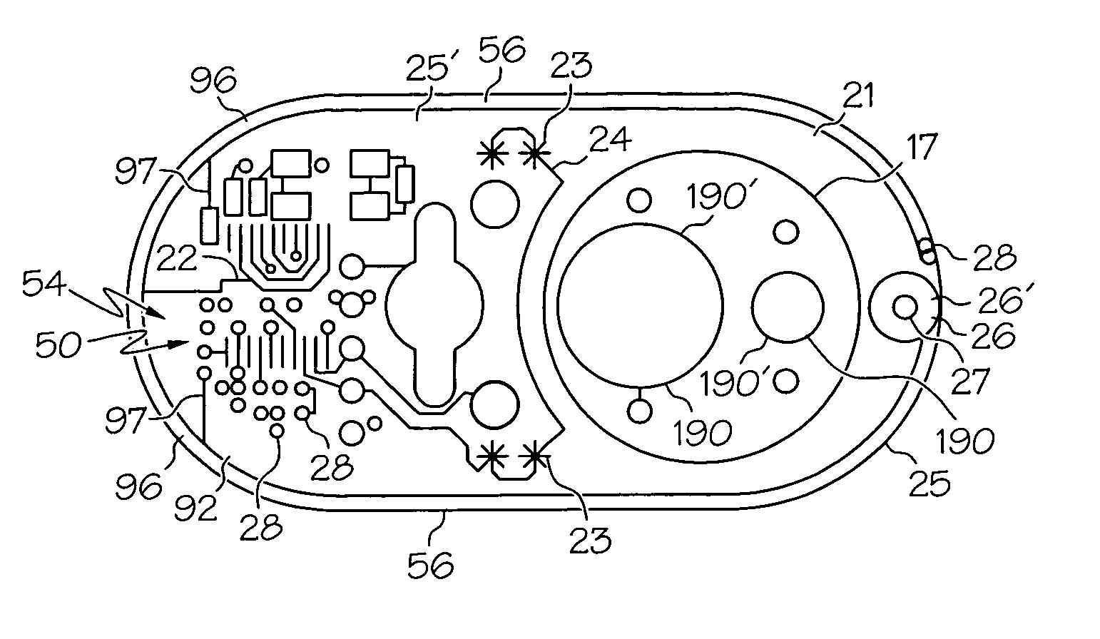
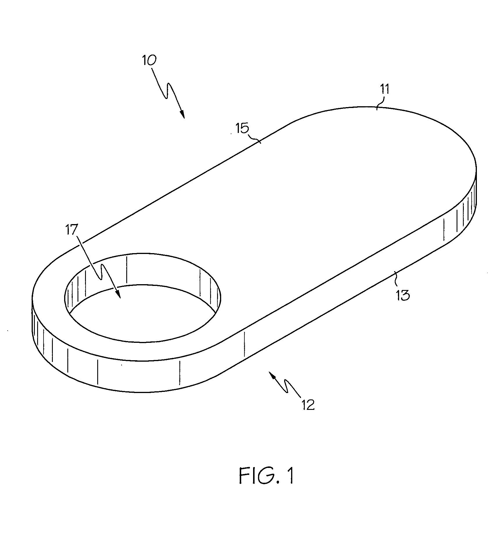
[0050]Device 10 according to this first embodiment is formed as a composite body 15 that contains at the least one event detection and reporting circuitry 50 (FIG. 2) that further comprises at least one event detection structure 35 (FIG. 5) and an RF circuit 54, such as a radio transmitter. In one preferred embodiment, device 10, according to the present invention, further includes at least one attachment structure 17. In this preferred embodiment, the attachment structure is an aperture or opening in the body 15 that is suitably sized to receive a projecting or elongate portion of the asset, such as a neck of a bottle or the like. Other structures that are capable of being received by the aperture 17, such as a suitably sized spheres and the like, are considered to fall within the scope of the present invention. Additionally, other attachment structures, both chemical or mechanical, that function to associate the body 15 to an asset may be used and are also considered to fall withi...

second embodiment

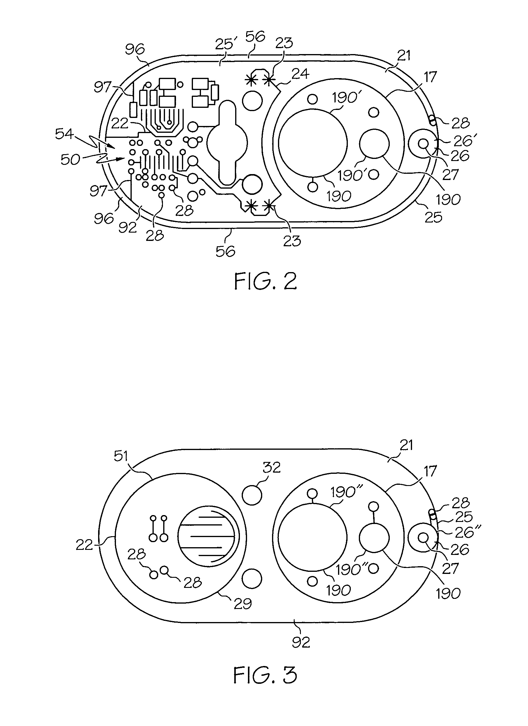
[0059]As can be seen from the simplified hardware diagram of electrical components of the RF apparatus presented in FIG. 8, the electrical circuit is preferably powered by a battery, most preferably a lithium coin cell. The battery is electrically connected to a microprocessor / transmitter that preferably has the microcontroller and transmitter physically integrated and a built in periodic wakeup mechanism, 1024 instructions of non-violate “code” memory, 41 bytes of violate “ram” memory, an RC oscillator and an integrated Real Time Reference. Electrically connected to the transmitter portion is loop antenna 25 and its associated antenna tuning capacitor 26. Also connected to the microcontroller are a crystal and, optionally, a push button that is electrically connected to an input pin of the microcontroller. Finally, there is at least one event detection structure 35 that is electronically connected to an input pin of the microcontroller. These features are discussed in more detail b...


PUM


Abstract

Described herein are a transient event detector (35) comprising electrical circuitry (50) suitable to detect a transient event, and a container (34) having a wall with at least two electrically conductive contacts (23, 44) electrically connected to the electrical circuitry (50), each of the at least two electrically conductive contacts (23, 44) being electrically isolated from each other, and a movable electrically conductive piece (36) that intermittently connects at least two of the at least two electrically conductive contacts when the electrically conductive piece (36) is in motion. An RF circuit (54) couples to a loop antenna (25) having a tuning capacitor (26) formed as conductive pads (26′, 26″) juxtaposed on opposing sides of a planar dielectric substrate (92). The tuning capacitor (26) has a hole (27) through it, and the hole has a size that is selected to cause the loop antenna (25) to exhibit a desired resonance frequency.

Description

RELATED INVENTION[0001]The present invention claims benefit under 35 U.S.C. 119(e) to “Inventory Systems and Methods,” U.S. Provisional Patent Application Ser. No. 60 / 551,191, filed 8 Mar. 2004, and to “Inventory Systems and Methods,” U.S. Provisional Patent Application Ser. No. 60 / 650,307, filed 3 Feb. 2005, both of which are incorporated by reference herein.[0002]The present invention is a continuation-in-part of “Asset Tag with Event Detection Capabilities,” Ser. No. 10 / 795,720, filed 8 Mar. 2004, by at least one inventor in common herewith, which is incorporated by reference herein.TECHNICAL FIELD OF THE INVENTION[0003]The present invention relates generally to radio-frequency (RF) apparatuses which use loop antennas and which use tuning capacitors to tune the loop antennas. In addition, the present invention relates to such RF apparatuses which are configured to operate as asset monitoring tags.BACKGROUND OF THE INVENTION[0004]The identification, measurement and / or control of p...

Claims


Application Information

Patent Timeline
Patent Type & Authority Patents(United States)
IPC IPC(8): G08B13/14G08B1/08G08B13/24G08B21/00
CPCG01C9/06G01C9/10H01H35/02G08B13/149G08B13/2402G01F13/006G01C2009/068G01C2009/107H01H1/16H01H1/60
Inventor MORRISON, CHRISTOPHER S.
Owner NUVO HLDG
Why Eureka
Try Eureka