Evaporator and refrigerator comprising same

a technology of evaporator and refrigerator, which is applied in the direction of defrosting, domestic cooling apparatus, application, etc., can solve the problems of direct cooling type refrigerator having the structure, the evaporator has not yet been proposed, and the condensation of moisture to develop to frost on the surface of the evaporator, so as to prevent the heat generated during defrosting

Active Publication Date: 2021-08-24
LG ELECTRONICS INC
View PDF16 Cites 0 Cited by
  • Summary
  • Abstract
  • Description
  • Claims
  • Application Information

AI Technical Summary

Benefits of technology

[0014]A third object of the detailed description is to provide a structure in which heat generated by a sheath heater is effectively used for removing frost deposited on an evaporator and transfer of heat generated by the sheath heater to a refrigerating chamber is prevented.
[0022]The insulating member may be disposed on a rear surface of the reflective member to prevent heat generated for defrosting from being introduced to the refrigerating chamber.
[0030]First, the sheath heater is disposed to be adjacent to at least one surface of the evaporator case on an outer side of the evaporator case and is driven (turned on / off) according to predetermined conditions to generate heat. Heat generated by the sheath heater is transferred to the evaporator case to melt frost deposited on the evaporator case. In this manner, according to the present disclosure, since a defrost time is reduced compared with the existing natural defrosting, freshness of food may be maintained and cooling efficiency, which is reduced due to frost, may be increased to reduce power consumption.
[0032]Third, since the reflective member is disposed to face the evaporator case with the sheath heater interposed therebetween, although a portion of heat generated by the sheath heater is oriented in a direction opposite to the evaporator case, the heat is reflected by the reflective member and transferred to the evaporator case, and thus, heat generated by the sheath heater may be effectively used.
[0033]In addition, since the insulating member is disposed on the rear surface of the reflective member and covers the partition dividing the freezing chamber and the refrigerating chamber, heat generated during defrosting may be prevented from being transferred to the refrigerating chamber.

Problems solved by technology

Meanwhile, a difference in relative humidity between a surface of the evaporator and ambient air may cause moisture to be condensed to develop to frost on the surface of the evaporator.
However, a direct cooling type refrigerator having the structure in which a defrost heater is applied to an evaporator has not yet been proposed.
Therefore, in the case of the direct cooling type refrigerator, in order to remove frost, natural defrosting must be performed for a predetermined period of time after forcibly turning off a compressor, causing inconvenience, and it is difficult to ensure freshness of food due to the long defrosting time.

Method used


Image

  • Evaporator and refrigerator comprising same
  • Evaporator and refrigerator comprising same
  • Evaporator and refrigerator comprising same

Examples


first embodiment

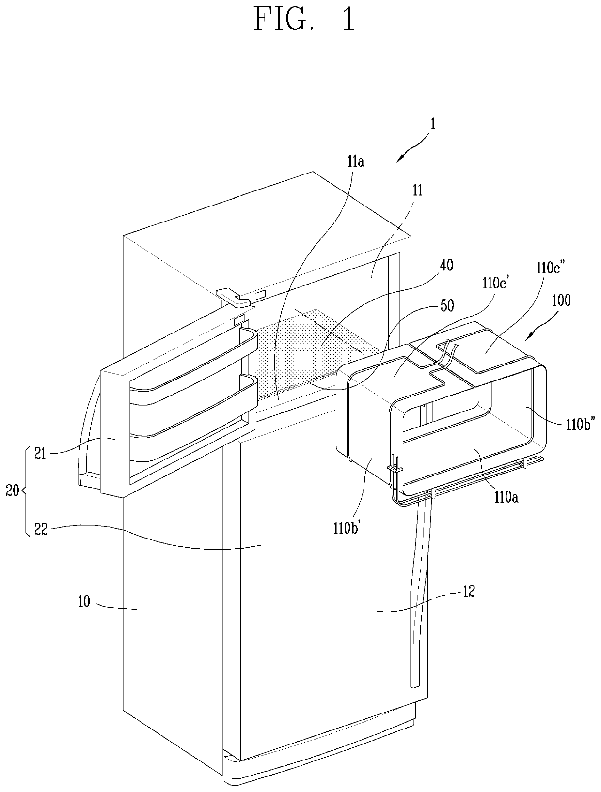
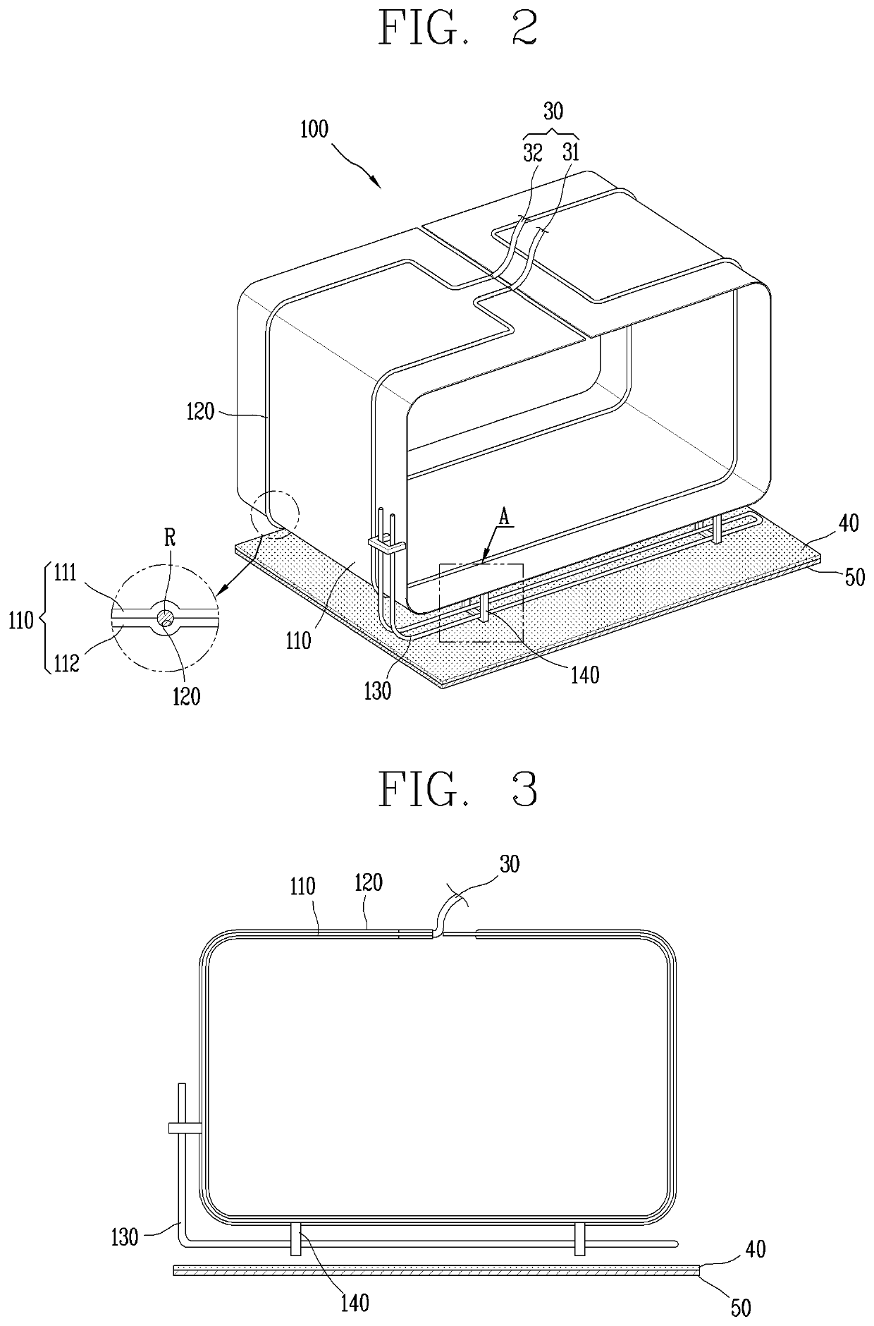
[0057]FIG. 2 is a conceptual view illustrating the evaporator 100 applied to the refrigerator of FIG. 1 and components related to defrosting of the evaporator, and FIG. 3 is a front view of the evaporator 100 illustrated in FIG. 2 and components related to defrosting of the evaporator 100.

[0058]Referring to FIGS. 2 and 3, the evaporator 100 of the present disclosure includes an evaporator case 110, a cooling tube 120, and a sheath heater 130. Among the components of the evaporator 100, the cooling tube 120 is a component for cooling, and the sheath heater 130 is a component for defrosting. For reference, the cooling tube 120 and the sheath heater 130 are illustrated briefly for convenience of explanation, and in actuality, these components may have various forms.

[0059]The evaporator case 110 is formed in an empty box shape and forms a storage space for food therein. The evaporator case 110 itself may form a storage space for food therein or may be configured to enclose a housing (no...

second embodiment

[0115]FIG. 6 is a conceptual view illustrating an evaporator 200 applied to the refrigerator 1 of FIG. 1 and components related to defrosting of the evaporator 200, and FIG. 7 is a view of the evaporator 200 and the components related defrosting of the evaporator 200 illustrated in FIG. 6, viewed in a VII direction.

[0116]Referring to FIGS. 6 and 7, a fixing member 250 includes a protrusion 251 protruding to one side of the sheath heater 230 from a lower surface of an evaporator case 210 and an extending portion 252 bent from the protrusion 251 and extending to cover the outside of the sheath heater 230. The fixing member 250 may be formed of a metal and fixed to the evaporator case 210 by welding.

[0117]According to the above-described configuration, the fixing member 250 has an ‘L’ shape and supports the sheath heater 230. The fixing member 250 may be provided in plurality, and the plurality of fixing members 250 may be spaced apart from each other at a predetermined distance and ma...

third embodiment

[0119]FIG. 8 is a conceptual view illustrating an evaporator 300 applied to the refrigerator 1 of FIG. 1 and components related to defrosting of the evaporator 300.

[0120]As illustrated, the evaporator case 310 may be partially cut and bent to form a fixing member 313. In this figure, a portion of a lower surface portion of an evaporator case 310 is cut and bent to fix the sheath heater 330 to below the lower surface portion.

[0121]The fixing member 313 includes a bent portion 313a and a recess portion 313b.

[0122]The bent portion 313a corresponds to a portion where the evaporator case 310 is partially cut and bent to the outside, and the recess portion 313b corresponds to a recessed space formed in the bent portion 313a to receive the sheath heater 330.

[0123]According to this structure, the sheath heater 330 may be received and supported in the recess portion 313b and fixed at a predetermined distance from the evaporator case 310. The fixing member 313 may be provided at a plurality ...


PUM


Abstract

A refrigerator includes a cabinet that defines a freezing compartment and a refrigerating compartment, and an evaporator installed in the freezing compartment. The evaporator includes: an evaporator case that defines a food storage space formed therein; a cooling tube located at the evaporator case in a predetermined pattern and configured to receive a coolant; and a sheath heater disposed outside of the evaporator case to be adjacent to at least one surface of the evaporator case, the sheath heater being configured to generate heat such that heat for defrosting is transferred to the evaporator case. The sheath heater reduces the defrosting time to maintain the freshness of food, increases the cooling efficiency, and reduces power consumption. The defrosting efficiency by the sheath heater is improved by a reflection member, and an inflow of heat, generated when defrosting, into the refrigerating compartment is reduced by a heat insulation member.

Description

CROSS-REFERENCE TO RELATED APPLICATIONS[0001]This application is a National Stage application under 35 U.S.C. § 371 of International Application No. PCT / KR2017 / 002269, filed on Mar. 2, 2017, which claims the benefit of Korean Application No. 10-2016-0034187, filed on Mar. 22, 2016. The disclosures of the prior applications are incorporated by reference in their entirety.BACKGROUND OF THE INVENTION1. Field of the Invention[0002]The present disclosure relates to an evaporator having a defrosting device for removing frost, and a refrigerator having the same.2. Description of the Related Art[0003]The refrigerator is a device for keeping food stored in the refrigerator at low temperatures using cold air generated by a refrigerating cycle in which a process of compression, condensation, expansion, and evaporation is continuously performed.[0004]A refrigerating cycle in a refrigerating chamber (or a refrigerating compartment) includes a compressor compressing a refrigerant, a condenser con...

Claims


Application Information

Patent Timeline
Patent Type & Authority Patents(United States)
IPC IPC(8): F25D21/08F25D19/00H05B3/48F25D21/06F25B39/02F25D13/04
CPCF25D21/08F25B39/022F25D13/04F25D19/00F25D21/06H05B3/48F25B39/02F25B2339/022
Inventor SHIN, YOUNGJAEKANG, WOOCHEOLLEE, GEUNHYUNGHWANG, GWINAN
Owner LG ELECTRONICS INC
Why Eureka
Try Eureka