Synthetic antenna sonar and method for forming synthetic antenna beams

a synthetic antenna and beam technology, applied in the field the detection and classification of objects by means of synthetic aperture sonar, can solve the problems of difficult to solve the question of object classification, determination of delays, and remains unsatisfactory, and achieve the effect of not, without reducing its detection and classification capabilities

Active Publication Date: 2021-09-07
THALES SA
View PDF12 Cites 0 Cited by
  • Summary
  • Abstract
  • Description
  • Claims
  • Application Information

AI Technical Summary

Benefits of technology

[0025]The proposed invention makes it possible to omit the auxiliary antenna. It also makes it possible not to decrease the resolution of the synthetic aperture sonar, i.e. without decreasing its detection and classification capabilities. In other words, the obtained resolution is comparable to that obtained by means of the method described in document FR 2769372, i.e. to the resolution obtained by means of a method using an autofocusing process in which the parasitic movements of the antenna are corrected for.

Problems solved by technology

The question of classification of objects is a problem that is difficult to solve especially for bottom mines placed on a textured seabed, or for stealth mines.
The use of a sonar in a very-high-resolution side-scan synthetic-aperture-sonar mode is one response to this problem, but one that remains unsatisfactory.
The main difficulty experienced when applying the synthetic-antenna principle resides in the determination of the delays to be used in the beam formation.
The longer this formation time, i.e. the higher the number of pings, which goes hand-in-hand with a better resolution, the more difficult it is to determine these delays.
Moreover, in this application it is observed that, in what are called autocalibrating or autofocusing processes, which allow the position of the antenna to be obtained by processing of the various signals measured by the antenna, the precision of the angle of rotation of the antenna between two pings is the factor limiting the precision of the process.

Method used


Image

  • Synthetic antenna sonar and method for forming synthetic antenna beams
  • Synthetic antenna sonar and method for forming synthetic antenna beams
  • Synthetic antenna sonar and method for forming synthetic antenna beams

Examples


Embodiment Construction

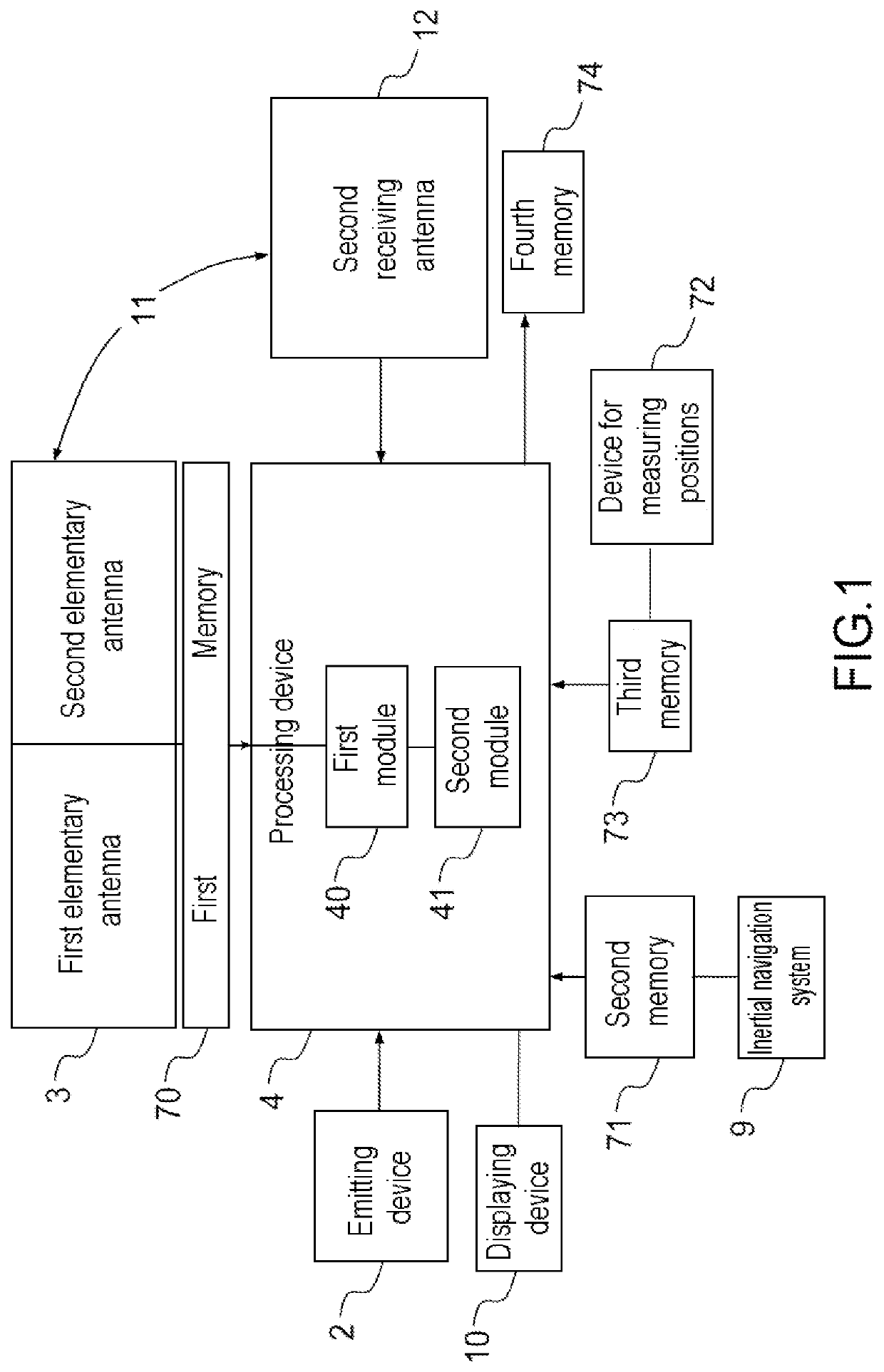
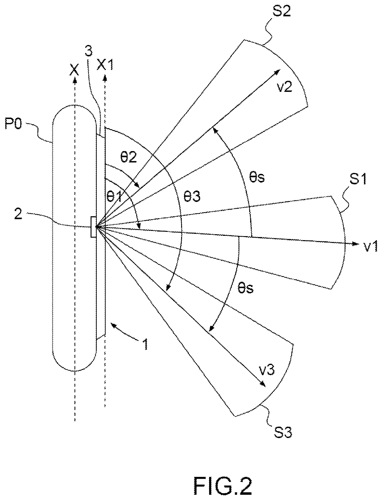
[0035]The invention relates to a mono-aspect or multi-aspect synthetic aperture sonar. By “mono-aspect synthetic aperture sonar”, what is meant is a synthetic aperture sonar intended to move along a first axis, the sonar comprising an emitting device configured to emit, in each ping, an acoustic pulse toward an observed zone in a single sector, the sonar comprising a first physical receiving antenna allowing measurements of backscattered signals generated by said pulse to be acquired and a processing device configured to form, over R pings, synthetic aperture beams from measurements of signals backscattered by the observed zone, which signals are generated by acoustic pulses emitted in said sector. The acoustic pulses are emitted along a single sighting axis in a single sector surrounding the sighting axis. This sighting axis may be attached to the antenna or be directed in a fixed direction in the terrestrial reference frame, for example by means of a stabilizing device. By “sector...


PUM


Abstract

A synthetic aperture sonar moving along a first axis comprises an emitting device configured to emit, in each ping, at least one acoustic pulse toward an observed zone in a set of sectors comprising at least one sector. The sonar comprises a first physical receiving antenna extending along the first axis allowing measurements of backscattered signals to be acquired and a processing device configured to form, over R pings, for each sector, synthetic aperture beams from measurements of signals backscattered by the observed zone and generated by acoustic pulses emitted in the sector. The sonar comprises at least one gyrometer. The processing device is configured to correct for variations in the movement of the first receiving antenna during the formation of the synthetic aperture beams of the set of sectors by carrying out an autocalibration by intercorrelation of the successive pings.

Description

CROSS-REFERENCE TO RELATED APPLICATIONS[0001]This application is a National Stage of International patent application PCT / EP2015 / 055334, filed on Mar. 13, 2015, which claims priority to foreign French patent application No. FR 1400614, filed on Mar. 14, 2014, the disclosures of which are incorporated by reference in their entirety.FIELD OF THE INVENTION[0002]The present invention relates to the field of sonar imaging and to the detection and classification of objects by means of a synthetic aperture sonar. It more particularly relates to mine warfare and to the detection and classification of mines by means of a synthetic aperture sonar.BACKGROUND[0003]The question of classification of objects is a problem that is difficult to solve especially for bottom mines placed on a textured seabed, or for stealth mines. The use of a sonar in a very-high-resolution side-scan synthetic-aperture-sonar mode is one response to this problem, but one that remains unsatisfactory. By “side-scan sonar”...

Claims


Application Information

Patent Timeline
Patent Type & Authority Patents(United States)
IPC IPC(8): G01S15/89G01S7/52
CPCG01S15/8904G01S7/52004
Inventor BURLET, NICOLASMANDELERT, NICOLASGUTHMANN, PIERRE
Owner THALES SA
Why Eureka
Try Eureka