Casting nozzle

a nozzle and casting technology, applied in the field of casting nozzles, can solve the problems of deterioration of sealing performance, forming gaps, and affecting the sealing performance so as to prevent or reduce the oxidation of the inner bore, prevent the occurrence of breaking of the upper end of the nozzle body, and prevent the leakage of molten steel

Active Publication Date: 2021-09-14
KROSAKI HARIMA CORP
View PDF9 Cites 0 Cited by
  • Summary
  • Abstract
  • Description
  • Claims
  • Application Information

AI Technical Summary

Benefits of technology

[0026]In the casting nozzle according to the present invention, the bridging segment is provided in at least a part of the gas pool to bridge between the outer peripheral surface of the upper end of the nozzle body and the inner peripheral surface of the metal casing. Thus, in the casting nozzle configured to form a gas pool between the outer peripheral surface of the upper end of the nozzle body and the inner peripheral surface of the metal casing, it is possible to suppress the occurrence of breaking of the upper end of the nozzle body. It is also possible to prevent or reduce oxidation of an inner bore of the casting nozzle and the vicinity of a joint portion with a lower nozzle, and erosion caused by iron oxide or the like, thereby preventing leakage of molten steel from the vicinity of the joint portion and deterioration in steel quality.
[0027]In one embodiment of the present invention where heat-resistant particles are filled in at least a part of the gas pool, the heat-resistant particles fulfill a function of dispersing stress, so that it is possible to suppress or prevent breaking of the upper end of the nozzle body.
[0028]In one embodiment of the present invention where the heat-resistant particles are bonded neither to each other nor to the nozzle body and the metal casing, even when deformation of the gas pool occurs, the heat-resistant particles themselves can be displaced to provide an effect of suppressing or preventing stress concentration.
[0029]In addition, it is only necessary to fill the heat-resistant particles in al least a part of the gas pool and restrain the filled part by a mechanical external force, e.g., by pressing. Thus, as compared with a case where a plurality of components are fixedly provided within the gas pool at respective positions, a production process becomes simpler and easier, so that it is possible to produce the casting nozzle within a shorter period of time at lower cost.

Problems solved by technology

In the joint portion between the lower nozzle and the long nozzle, the tight contact performance is likely to be deteriorated due to the detaching and re-attaching work, adhesion of molten steel, slag, etc., damage to the nozzles, and others, resulting in formation of a gap.
The formation of a gap leads to deterioration in sealing performance, which raises a risk that air is drawn inside the nozzles to cause oxidation of molten steel, damage to the nozzles due to oxidation when the nozzles are made of a carbon-containing refractory material, etc.

Method used


Image

  • Casting nozzle
  • Casting nozzle
  • Casting nozzle

Examples


first embodiment

Practical Examples of First Embodiment

Practical Example A

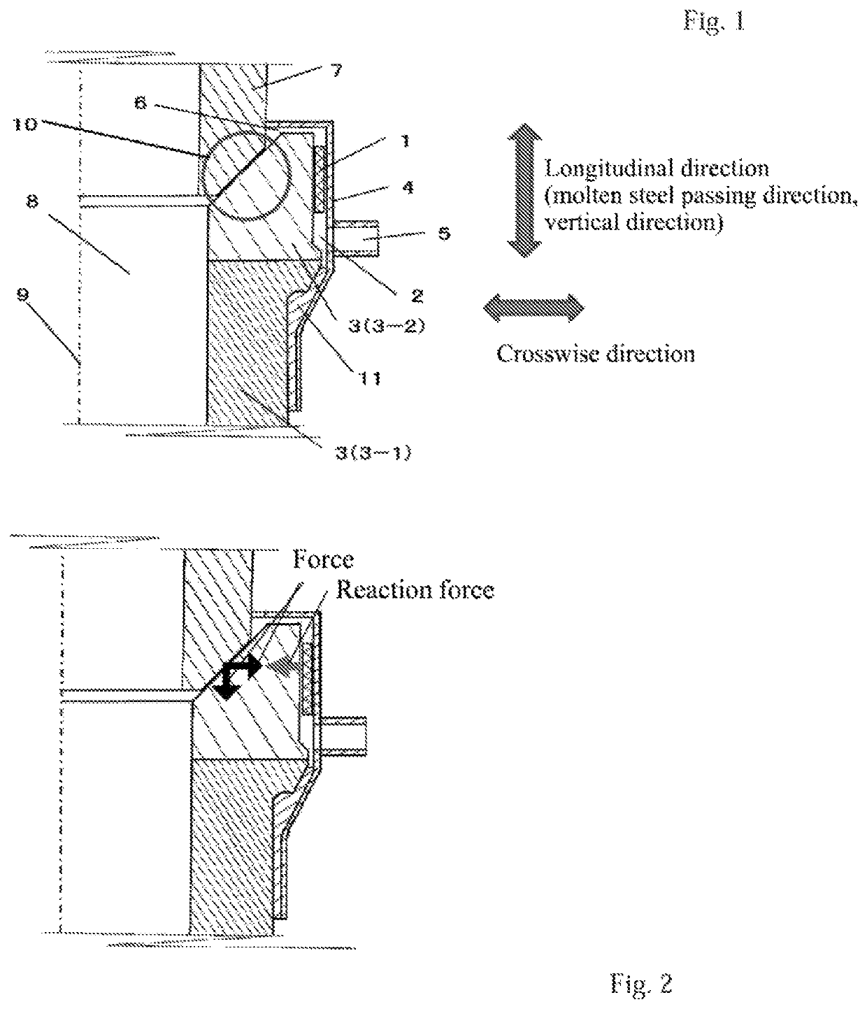
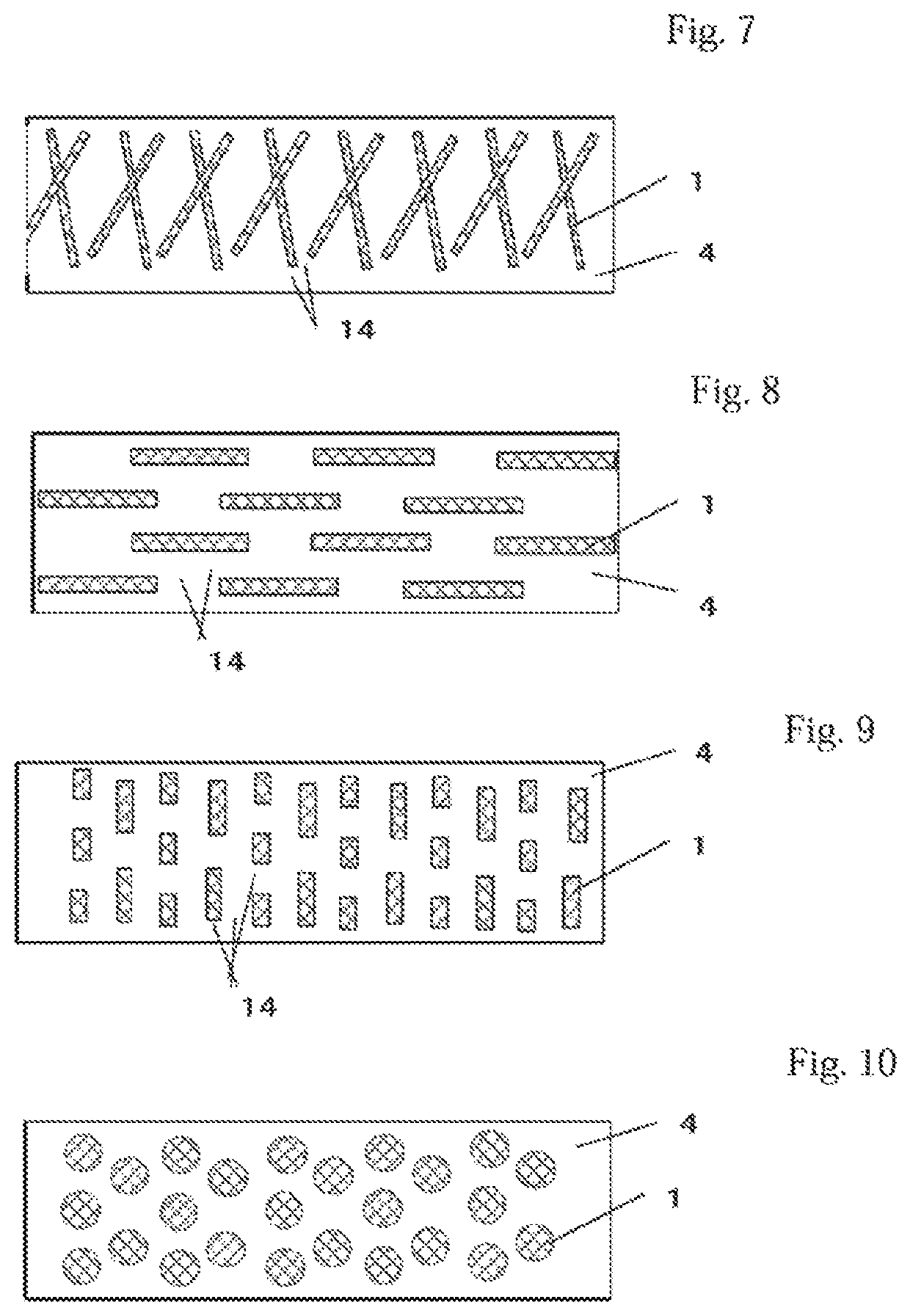
[0063]A practical example A is an example in which, in the structure shown in FIG. 1, the bridging segment is composed of eight round iron bars, wherein the round iron bars are arranged at respective positions on the circumference of the inner peripheral surface of the metal casing and weldingly joined to the metal casing in a state in which each of them extends in a direction parallel to the longitudinal direction of the long nozzle body (i.e., in the longitudinal direction).

[0064]In actual casting operation using a conventional structure devoid of the bridging segment (i.e., a comparative example (structure obtained by removing the bridging segment 1 from the structure (practical example A) in FIG. 1), longitudinal cracking or braking due to splitting caused by the cracking occurred in the long nozzle body. On the other hand, in actual casting operation using the long nozzle of the practical example A according to the first ...

second embodiment

[0068]In a second embodiment of the present invention, heat-resistant particles 1A are filled in at least a part (a part or substantially the entire region of) the gas pool 2, as exemplified in FIG. 12, and the bridging segment 1 is composed of the filled heat-resistant particles 1A. Then, this bridging segment 1 functions to restrain the outer peripheral surface of the nozzle body 3 in the radial direction as mentioned above, and the heat-resistant particles 1A composing the bridging segment 1 brings out a stress dispersion effect.

[0069]In the second embodiment, preferably, the heat-resistant particles 1A are filled (restrained) within the gas pool (in substantially the entire region of the gas pool) in a state in which they are bonded (joined) neither to each other nor to any of the surfaces defining the gas pool (gas pool-defining surfaces), although some of them are in contact with the surfaces. That is, preferably, the heat-resistant particles 1A are restrained mutually and bet...


PUM

PropertyMeasurementUnit
particle sizeaaaaaaaaaa
temperatureaaaaaaaaaa

Abstract

Disclosed is a casting nozzle intended to suppress or prevent breaking of a nozzle body thereof. The casting nozzle comprises: a nozzle body; a metal casing disposed to surround an upper end of the nozzle body to form a gas pool between an outer peripheral surface of the upper end of the nozzle body and an inner peripheral surface of the metal casing; and a bridging segment provided in at least a part of the gas pool to bridge between the outer peripheral surface of the upper end of the nozzle body and the inner peripheral surface of the metal casing.

Description

TECHNICAL FIELD[0001]The present invention relates to a casting nozzle for use in continuous casting of molten steel.BACKGROUND ART[0002]In continuous casting of molten steel, as a means to discharge molten steel from a ladle to a tundish, a long nozzle as a casting nozzle is commonly used so as to suppress oxidation of molten steel, and entrainment of slag on an upper surface of molten steel within the tundish into the molten steel. On the other hand, as a means to pour molten steel from the tundish to a mold, an immersion nozzle as a casting nozzle is commonly joined beneath a lower nozzle attached to the bottom of the tundish.[0003]The following description will be made by mainly taking the long nozzle as an example of a casting nozzle.[0004]The long nozzle is joined to a lower nozzle installed to the bottom of the ladle through a packing (sealing) member or the like. Between the lower nozzle and the long nozzle, a high level of tight contact performance (sealing performance) is ...

Claims


Application Information

Patent Timeline
Patent Type & Authority Patents(United States)
IPC IPC(8): B22D41/58B22D11/10
CPCB22D41/58B22D11/10B22D11/047B22D41/502
Inventor HARADA, TAKAFUMITACHIKAWA, KOUICHI
Owner KROSAKI HARIMA CORP
Why Eureka
Try Eureka