System and method for sub-grade stabilization of railroad bed

a subgrade and subsoil technology, applied in ballastways, constructions, ways, etc., can solve the problems of increasing the complexity and cost of railway maintenance and repair, the inability to specifically target the subgrade or subsoil of repair, and the time-consuming process of loading, unloading and reloading equipment, so as to reduce the ability of subgrade and ballast maintenance, reduce the dynamic load of bridges, and increase the dynamic load

Active Publication Date: 2021-09-14
SOIL-NAIL HLDG LLC
View PDF24 Cites 1 Cited by
  • Summary
  • Abstract
  • Description
  • Claims
  • Application Information

AI Technical Summary

Benefits of technology

[0010]According to one preferred embodiment, the invention is a method of installing subsurface inclusions comprising injected slurry mixtures of stabilizing material such as cement grout mixed with in situ soil. The inclusions may substantially increase subgrade bearing capacity and shear strength. The inclusions when installed are in the general shape of a cylindrical column with a selected diameter and depth depending upon the subsurface and subsoil conditions to be repaired. One example range for the diameter of the inclusions is 8 to 16 inches in diameter. One example range for the depth of the inclusions may be 10 to 30 feet deep.
[0015]Inclusions and ballast fills in one aspect may communicate with one another so there is a continuous amount of slurry mix which interconnects one or more inclusions and a ballast fill. Alternatively, a ballast fill may be installed as a single support element in situations where the subgrade beneath the ballast pocket may be stable and therefore does not require an inclusion.
[0017]According to another preferred embodiment of the invention, it includes a method of installing a selected array of ground inclusions and ballast fills for a rail bed. According to one aspect of this method, holes are selectively drilled within the subgrade and / or subsoil to emplace a selected number and spacing of inclusions. Ballast fills are selectively located at the locations of corresponding ballast pockets such that the ballast fills eliminate spaces defined by the ballast pockets that typically hold water and cause track instability. The ground inclusions and ballast fills may include cement grout, a slurry mixture of cement grout and soil, or other combinations of materials. In areas where there is frequent train traffic, the injection of the repair material may be accelerated so that installed inclusions may obtain initial sets within 30 minutes to 2 hours depending on dosages and traffic windows available for injection. The inclusions will not be degraded by train traffic within this initial cure period. Preferably, the top of the inclusions are terminated at the bottom portion of the clean ballast, which may be approximately 2-3 feet below the track to ensure that the track bed loads are distributed over the inclusion array and to prevent over stressing individual cross ties or track works or fouling clean ballast and reducing the ability of subgrade and ballast maintenance by railroad personnel. However, it should be understood that the depth of termination for the inclusions can be adjusted to specific ground conditions, railroad specifications or preferences. Depending upon the degree to which ballast is displaced during emplacement of inclusions and ballast fills, some amount of track surfacing may be necessary to reshape the upper ballast layer or level the track.
[0018]According to another aspect of the method of installing the system, the system can be employed within bridge abutments thereby reducing dynamic loads on bridges and the abutments themselves. The presence of ballast pockets or otherwise failing subgrade conditions at bridge abutments results in sometimes significant increases in dynamic loads experienced by the bridge as train traffic passes. Bridge transition design can be improved by emplacing the system which may include gradually increasing inclusion array density and depth as the track approaches the bridge. The increasing subgrade strength and subgrade modulus approaching the bridge will ease the stiffness differential between a track embankment and the bridge structure itself. In this way, the rail track is further stabilized to prevent movement caused by dynamic loading from passing train traffic.
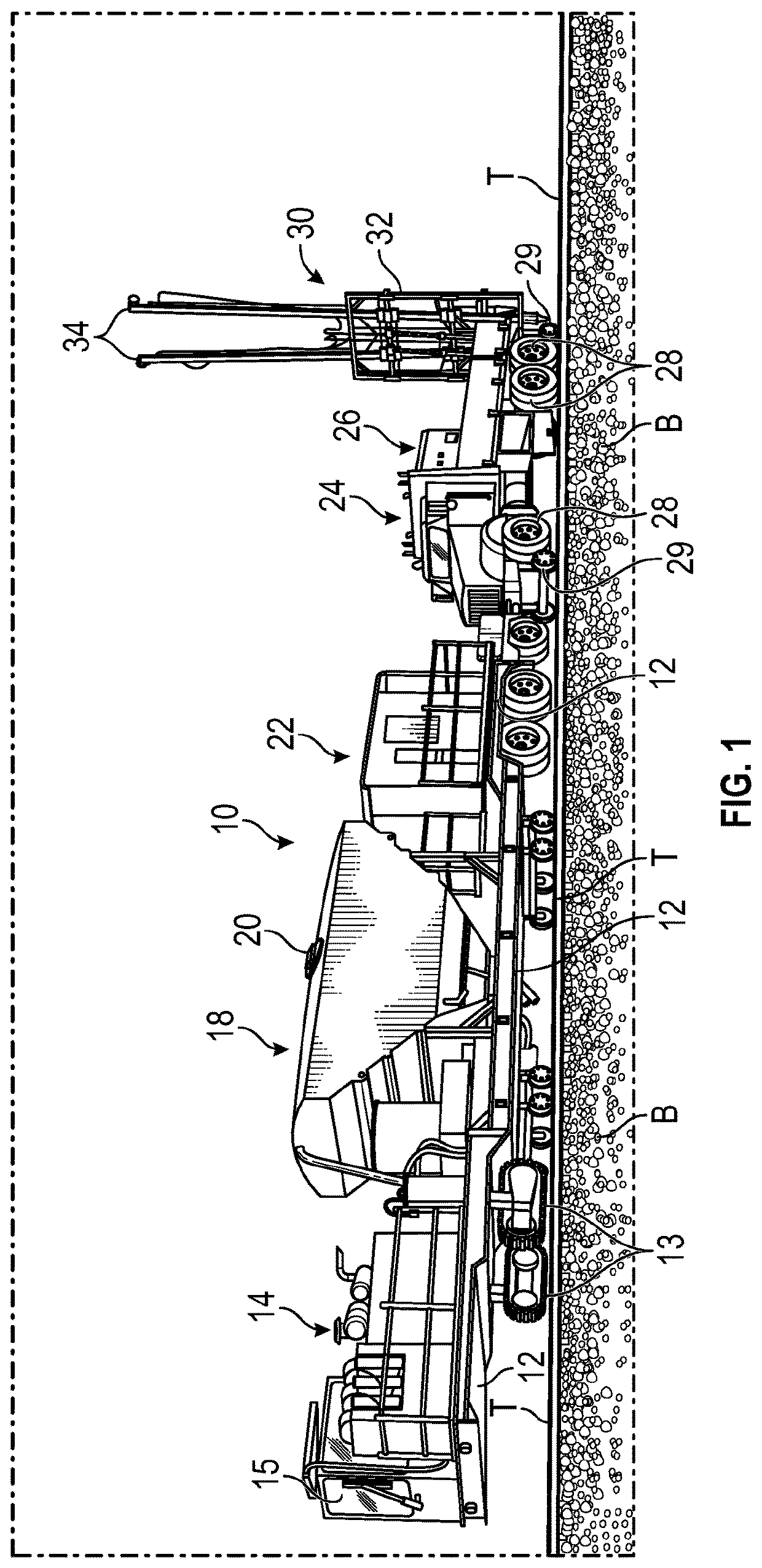
[0019]There are many advantages to the systems and methods of the invention. An economical and efficient solution is provided for improving the stability of soft subgrades thereby substantially reducing overall maintenance costs as well as minimizing interruption to railway traffic or operations. The injected grout material will not foul clean ballast. Therefore, there is no subsequent requirement to clean or replace ballast. There is no waste product produced because the material to be injected is mixed real-time within minutes of being pumped into the ground. All of the equipment is hi-rail mounted and is self sufficient. External or supplemental equipment is not required for any job thereby making the invention a global solution for subgrade and subsoil stabilization. The system of equipment is configured so that access to a desired rail is possible that typical to rail crossings similar to a hi-rail dump truck. Therefore, no support is required from railroad personnel other than basic track protection measures.
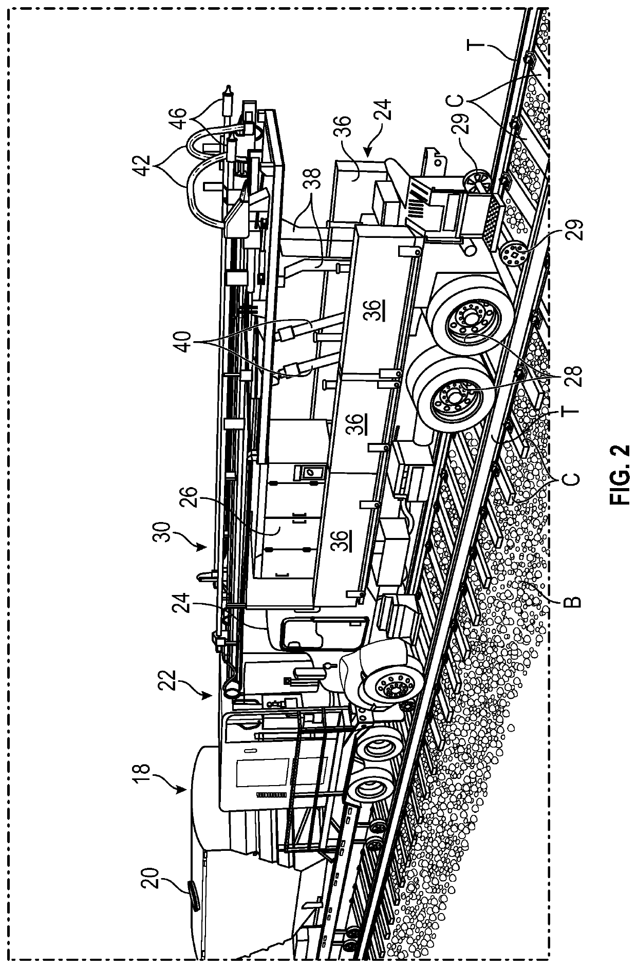
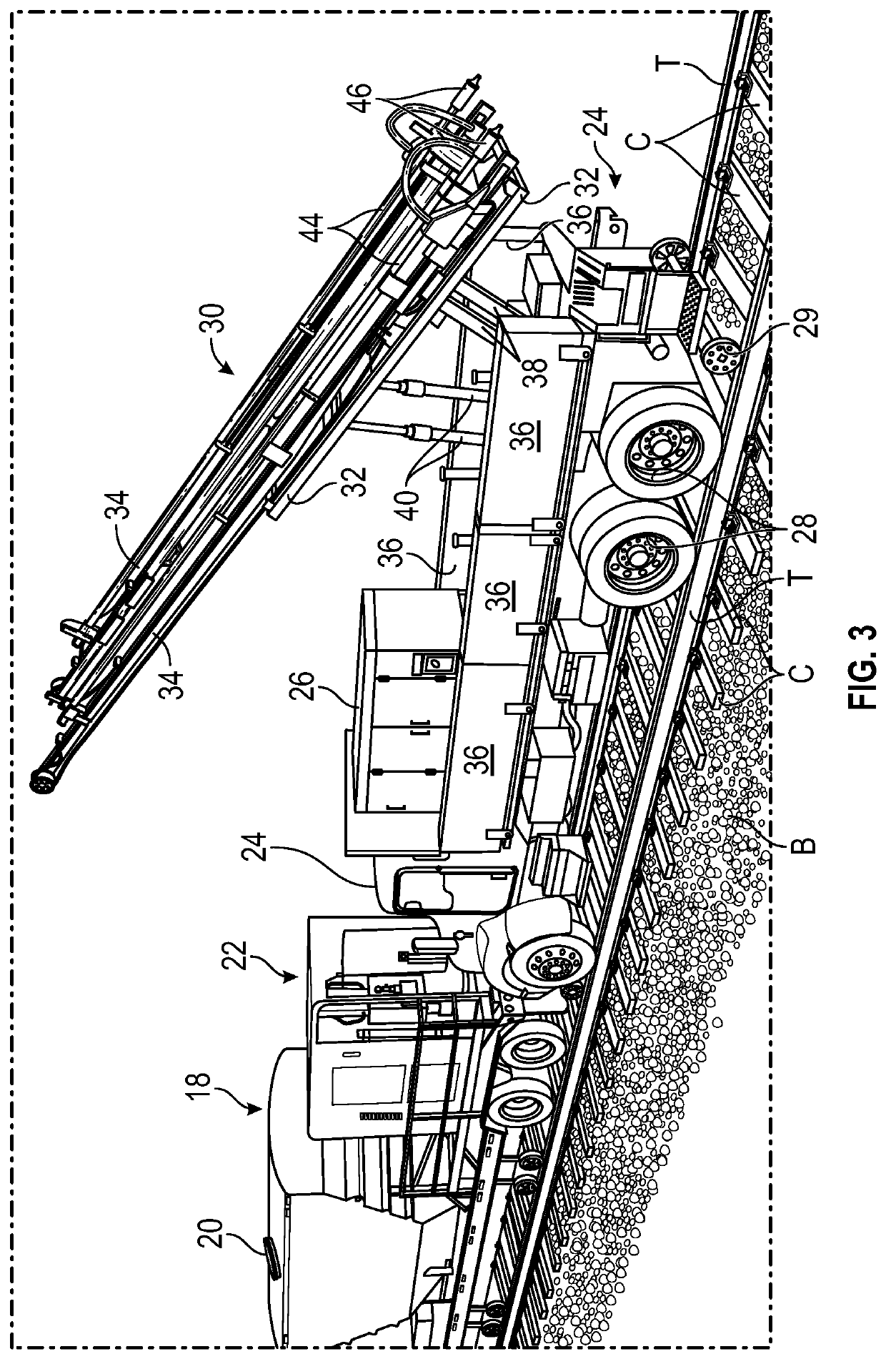
[0024]According to another aspect of the invention, it may be considered a method for stabilizing subgrade and subsoil ground layers of a railroad bed underlying a railroad having rails and cross ties, the method comprising: providing a rail mounted vehicle, a drill mast mounted on the vehicle, the drill mast having at least one drill and a corresponding drill head; determining a location on the railroad where the subgrade or subsoil have failed causing destabilization of the ballast upon which the rails and cross ties lie; predetermining an array of inclusions to be emplaced to stabilize the subgrade and / or subsoil, the predetermining step including a measure of a distance and depth for an area to be stabilized at the location; positioning the at least one drill over a first position and forming at least inclusion; automatically moving the at least one drill to a subsequent second position and forming another inclusion according to the predetermined array.

Problems solved by technology

Considering the extensive railway networks in many countries that continue to expand, railway maintenance and repair has become an increasingly complex and costly.
The process of loading, unloading, and reloading the equipment is time-consuming.
Accordingly, the repair cannot specifically target just the subgrade or subsoil because overlying layers must be first removed for many repair tasks.
Another significant drawback to existing solutions is that creating lateral access to the rail bed by undercutting the rail bed and emplacing stabilization material is in many cases merely a temporary solution.
The long-term problem is the failure of the subgrade, subsoil, or both.
Therefore, the packing of material to replace missing material such as within a ballast pocket by an undercut access method does not improve subgrade / subsoil conditions.
Subsequent destabilization of the rail bed will ultimately occur with further and continued settling or failure of the subgrade or subsoil.

Method used


Image

  • System and method for sub-grade stabilization of railroad bed
  • System and method for sub-grade stabilization of railroad bed
  • System and method for sub-grade stabilization of railroad bed

Examples


Embodiment Construction

[0045]FIG. 1 is a perspective view of the rail mounted system of the invention including a depiction of major components or pieces of equipment making up a system 10 mounted on a railroad with tracks T. The major components of the equipment comprise three elements mounted on a trailer 12 illustrated as an engine 14, a cement silo 18, and a combined jet grout mixer and a pump unit 22. The other major component includes a hi-rail truck 24 and a drill mast assembly mounted to the truck 24.

[0046]The trailer 12 has drive tracks 13 that are propelled by the engine 14. A cab 15 is provided for an operator to control the engine 14. The cement silo 18 holds a desired quantity of cement grout mix in preparation for installation of the ground inclusions and ballast fills. An inlet port 20 allows for charging the cement silo with the grout materials. The jet grout mixer and pump unit 22 are employed to mix the grout materials received from the cement silo 18 and to convey the mixed grout to a d...


PUM


Abstract

The invention is a system and method for repairing, improving, and stabilizing subgrade and subsoil / natural ground layers of a rail bed generally consisting of softer soils. One embodiment includes a method of installing subsurface inclusions and ballast fills comprising injected slurry mixtures of stabilizing material such as cement grout mixed with in situ soil. Another embodiment includes a system of installed ground inclusions and ballast fills. Another embodiment includes an integrated system of equipment for emplacing the system of inclusions and ballast fills.

Description

FIELD OF THE INVENTION[0001]The invention relates to maintenance and repair of railroad or track beds, and more particularly, to a system and method for repairing and stabilizing subgrade and subsoil / natural ground layers of a railroad bed.BACKGROUND OF THE INVENTION[0002]Railroad lines traverse hundreds of thousands of miles across the US and other countries. As time has progressed, railroad transportation has evolved into use of trains with greater load carrying capacity and speed. Increased railway traffic is common in many areas. Considering the extensive railway networks in many countries that continue to expand, railway maintenance and repair has become an increasingly complex and costly.[0003]A typical construction for a rail bed includes a formed subgrade and one or more ballast layers. The upper layer of clean ballast stabilizes the network of cross ties and rails. Depending upon drainage requirements, the subgrade and ballast layers may extend above the adjacent ground sur...

Claims


Application Information

Patent Timeline
Patent Type & Authority Patents(United States)
IPC IPC(8): E01B37/00E01B27/10E01B2/00E01B1/00
CPCE01B27/102E01B1/001E01B2/006E01B37/00E01B2204/03
Inventor SZYNAKIEWICZ, TOMASZANDERSON, JUSTINHOLLINGER, ROBERT W.
Owner SOIL-NAIL HLDG LLC
Why Eureka
Try Eureka