
Machine system for co-production of electrical power and water and method of operating same

a technology of electrical power and water, which is applied in the direction of machines/engines, separation processes, and filtration treatment, etc., can solve the problems of long time-consuming and laborious, difficult to provide resources to remote work locations, and other regions experiencing natural or man-made disasters

Active Publication Date: 2021-09-14
CATERPILLAR INC
View PDF57 Cites 3 Cited by
  • Summary
  • Abstract
  • Description
  • Claims
  • Application Information

AI Technical Summary

Problems solved by technology

Provision of resources to remote work locations, underdeveloped regions of the world, or other regions experiencing natural or manmade disasters has long been challenging to governments, business entities, and non-governmental organizations.

Method used


Image

  • Machine system for co-production of electrical power and water and method of operating same
  • Machine system for co-production of electrical power and water and method of operating same

Examples


Embodiment Construction

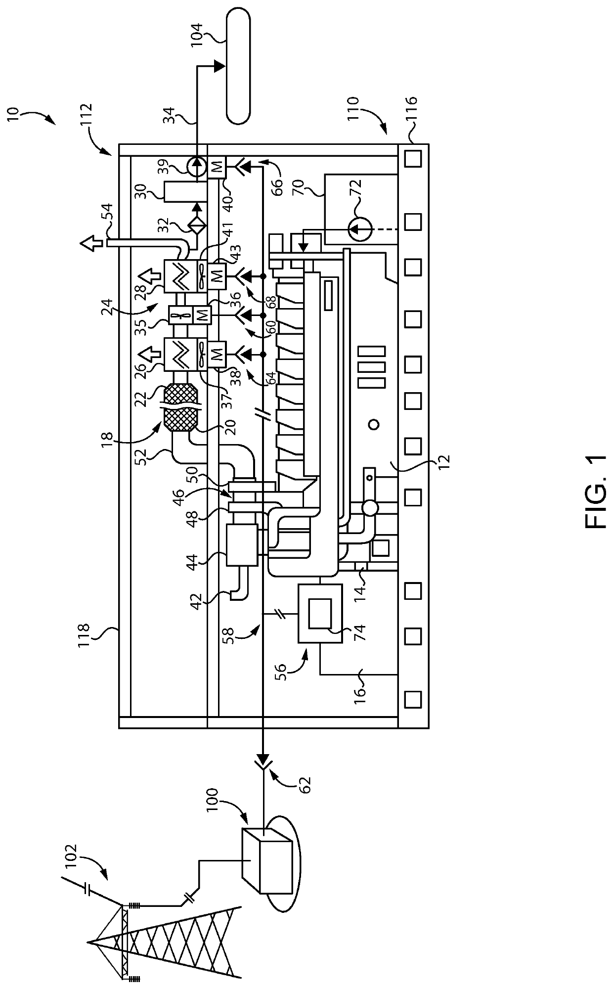
[0008]Referring to FIG. 1, there is shown a machine system 10 for co-production of electrical power and water, according to one embodiment. Machine system 10 can be deployed at a remote work location, in a disaster-stricken area, or in another application where provision of both electrical power and potable water is desirable, although the present disclosure is not limited to any particular regional or situational application. Machine system 10 includes an internal combustion engine 12 having an engine output shaft 14. Internal combustion engine 12 (hereinafter “engine 12”) may include a multi-cylinder compression-ignition liquid-fuel engine, such as a diesel engine, although the present disclosure is not thereby limited. In other instances, engine 12 could include a spark-ignited or prechamber-ignited gasoline or natural gas engine, a liquid fuel engine operated on biodiesel or a blended liquid fuel, a dual fuel engine, or still another type of combustion engine.

[0009]Engine output...


PUM

PropertyMeasurementUnit
electrical poweraaaaaaaaaa
electricalaaaaaaaaaa
pressureaaaaaaaaaa

Abstract

Operating a machine system for co-production of electrical power and filtered potable water includes operating an electrical generator by way of rotation of an engine output shaft to produce electrical power, and collecting water condensed from cooled treated exhaust from the engine for delivery to an outgoing water conduit. Operating the machine system further includes supplying electrical power produced by the electrical generator to an in situ electrical load, and to at least one ex situ electrical load such as a power grid. The in situ electrical load is produced by at least one of an exhaust conveyance device, an air conveyance device, or a water conveyance device in a water subsystem.

Description

TECHNICAL FIELD[0001]The present disclosure relates generally to a machine system for co-production of electrical power and water, and more particularly to operating equipment in a water subsystem condensing water from engine exhaust, using electrical power produced by an electrical generator operated by the engine.BACKGROUND[0002]Provision of resources to remote work locations, underdeveloped regions of the world, or other regions experiencing natural or manmade disasters has long been challenging to governments, business entities, and non-governmental organizations. Many such regions rely upon local grids subject to supply interruptions for electrical power, and thus consistent electrical power is sometimes unavailable. Various mobile electrical power units, mobile field hospitals, and temporary infrastructure apparatus are known which can theoretically be deployed on an as-needed basis. Engineers and other persons skilled in the field of disaster relief are routinely developing n...

Claims


Application Information

Patent Timeline
Patent Type & Authority Patents(United States)
IPC IPC(8): F01N3/00F01N3/04F02B63/04F01N3/033F01N3/28F01N3/02B01D53/00F01N3/035F01N3/05C02F1/16
CPCF01N3/005B01D53/002C02F1/16F01N3/0205F01N3/033F01N3/035F01N3/043F01N3/055F01N3/2889F02B63/042C02F2201/008C02F2201/009F01N2240/02F01N2240/22F01N2250/02F01N2250/10F01N2260/024F01N2570/22F02B2201/02B01D53/265B01D2258/01C02F1/004C02F2303/10F01N3/021F01N3/20F02B63/044Y02T10/12Y02W10/30
Inventor COLDREN, DANA RAY
Owner CATERPILLAR INC
Learn More