Ring section pump having intermediate tie rod combination

a tie rod and ring section technology, applied in the field of pumps, can solve the problems of short span of tie rods, inability to resist twisting of ring section assembly, and current design limitations, so as to improve the alignment of components of the pump, reduce the span, and facilitate the measurement of alignment

Active Publication Date: 2021-09-14
ITT MFG ENTERPRISES LLC
View PDF34 Cites 0 Cited by
  • Summary
  • Abstract
  • Description
  • Claims
  • Application Information

AI Technical Summary

Benefits of technology

[0006]Assembly difficulty is alleviated by the present invention by reducing the span between tie-rod ends. The assembly process is safer due to the reduction of unsupported stages before installing tie-rods. This also results in better component alignment for the pump and easier measurement of alignment between shorter spans.
[0007]The present invention also provides a solution to potential structural vibration problems. This arrangement allows for greater options for changing natural frequency of pump structure to reduce resonant vibrations. The present invention is an optimized solution to pressure handling capabilities of the ring-section pump. This allows for a reduction of tie-rods for low pressure sections of the pump. Also this allows an increase in stages and pressure handling without costly material addition. The invention also reinforces the pump assembly more in the region that the ring-sections experience the highest between ring-section torque (force trying to spin sections relative to each other).Specific Embodiments of the Present Invention

Problems solved by technology

This solution is adequate for shorter pumps; however, for longer pumps this arrangement becomes difficult to assemble, subject to more resonant vibration problems and costly due to tie rods having to handle the full pressure of the whole pump.
Long spans of tie rods are also less able to resist twisting of ring section assembly.
In effect, the current design is limited to only a single size of tie-rod that spans the entire length of pump assembly.

Method used


Image

  • Ring section pump having intermediate tie rod combination
  • Ring section pump having intermediate tie rod combination
  • Ring section pump having intermediate tie rod combination

Examples


Embodiment Construction

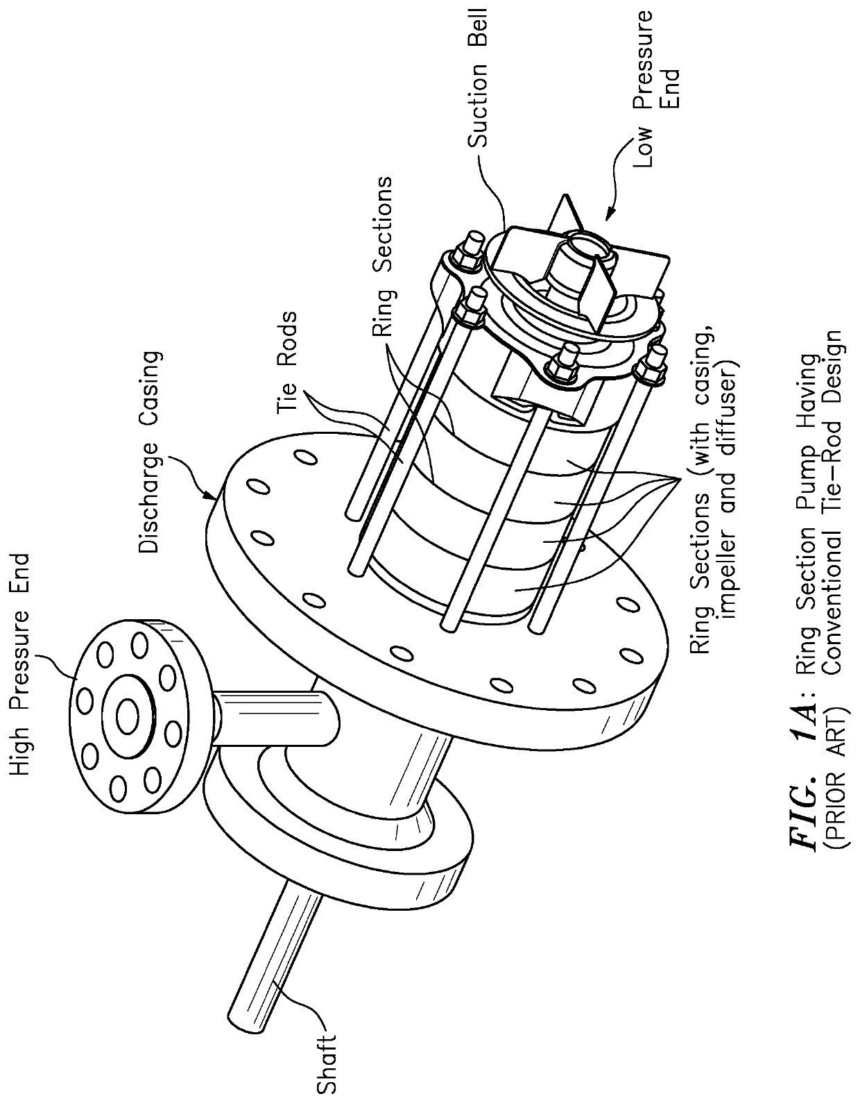
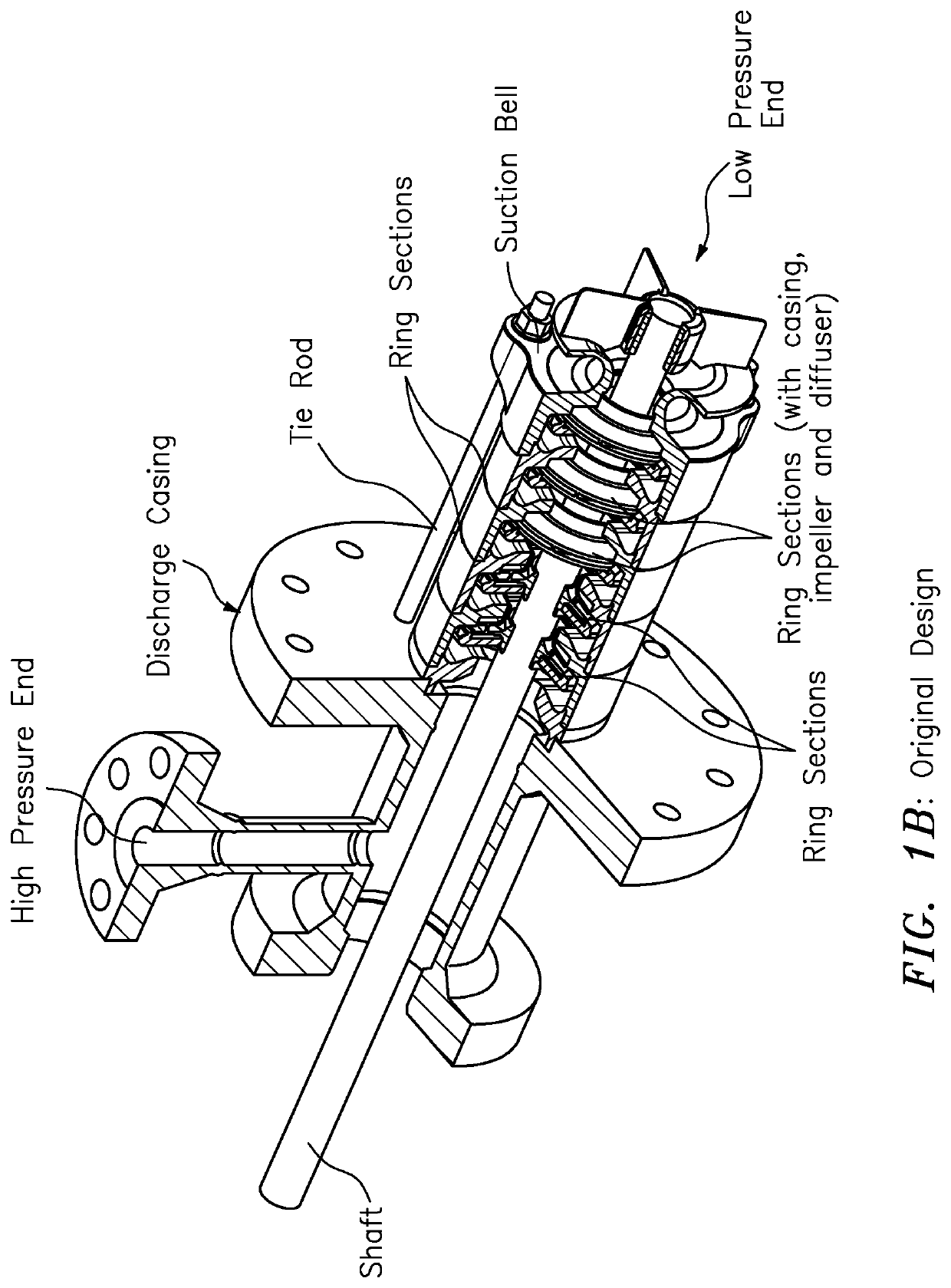
[0008]According to some embodiments, the present invention may take the form of apparatus, e.g., including a ring section pump, featuring[0009]a low-pressure end configured to receive fluid to be pumped into the ring section pump;[0010]high-pressure end configured to provide the fluid to be pumped from the ring section pump; and[0011]at least one intermediate tie rod combination having at least one intermediate flange with upper tie rods configured to couple together the at least one intermediate flange and the high-pressure end and with lower tie rods configured to couple together the at least one intermediate flange and the low-pressure end.

[0012]The apparatus may include one or more of the following features:

[0013]The low-pressure end may include an inlet flange; the high-pressure end may include an outlet / discharge flange; and the upper tie rods may couple together the at least one intermediate flange and the outlet / discharge flange, and the lower tie rods may couple together th...


PUM


Abstract

A ring section pump features a low-pressure end configured to receive fluid to be pumped into the ring section pump; a high-pressure end configured to provide the fluid to be pumped from the ring section pump; and an intermediate tie rod combination having a intermediate flange with upper tie rods configured to couple together the intermediate flange and the high-pressure end and with lower tie rods configured to couple together the intermediate flange and the low-pressure end. The low-pressure end has an inlet flange; the high-pressure end has an outlet / discharge flange; and the upper tie rods couple together the intermediate flange and the outlet / discharge flange and the lower tie rods couple together the intermediate flange and the inlet flange.

Description

BACKGROUND OF THE INVENTION1. Field of the Invention[0001]This application relates to a pump; and more particularly to a ring section pump having tie rods.2. Brief Description of Related Art[0002]By way of example, FIGS. 1A and 1B and FIGS. 2A and 2B show ring section tie-rod pump that are known in the art. FIGS. 1A and 1B show a ring section tie-rod pump, e.g., that may be vertically arranged, mounted and used in relation to a sump. In comparison, FIGS. 2A and 2B show a ring section tie-rod pump, e.g., that may be horizontally-mounted and used in relation to other pumping applications.[0003]Traditional ring section tie-rod pumps are built with tie-rods extending the full length of all stages. This solution is adequate for shorter pumps; however, for longer pumps this arrangement becomes difficult to assemble, subject to more resonant vibration problems and costly due to tie rods having to handle the full pressure of the whole pump. Long spans of tie rods are also less able to resis...

Claims


Application Information

Patent Timeline
Patent Type & Authority Patents(United States)
IPC IPC(8): F04C19/00F04D1/06F04D29/62F04C7/00
CPCF04C19/005F04C7/00F04C19/001F04D1/066F04D29/628F04C2240/20F05D2260/31F05D2210/11
Inventor MILLER, DANIEL S.GANDHI, ABHI N.BEHNKE, PAUL W.
Owner ITT MFG ENTERPRISES LLC
Why Eureka
Try Eureka