
Temperature measuring device and measurement alignment method thereof

a technology of temperature measurement and measurement alignment, which is applied in the direction of optical radiation measurement, diagnostic recording/measuring, instruments, etc., can solve the problems of measurement uncertainty, affecting the temperature measurement, and the measurement device does not calculate the temperature value in consideration, so as to prevent inaccurate temperature measurement

Active Publication Date: 2021-09-14
AVITA
View PDF22 Cites 0 Cited by
  • Summary
  • Abstract
  • Description
  • Claims
  • Application Information

AI Technical Summary

Benefits of technology

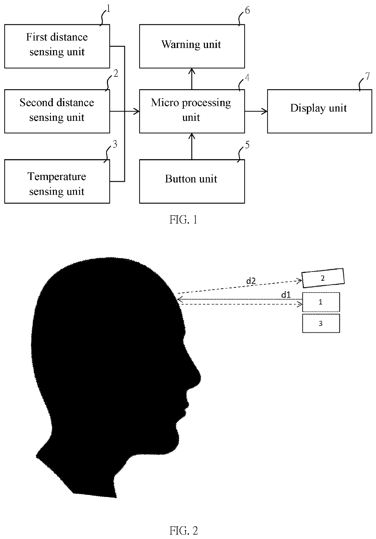
[0006]An objective of the present invention is that at least two distance sensing units are used to prevent the temperature measurement from being performed when the measurement angle by which the sensing unit of the thermometer obliquely points to the to-be-sensed part of the to-be-measured target is too large.
[0028]When using the temperature measuring device and the measurement alignment method of the present invention, the user can evaluate the measurement angle of the to-be-sensed part of the to-be-measured target to which the sensing unit points, according to the distance sensing results of the at least two distance sensing units, so as to prevent from inaccurate temperature measurement because the temperature measurement angle is shifted when the user operates the thermometer. As a result, the temperature measurement result can be maintained as a temperature measurement value with acceptable accuracy; furthermore, the temperature measuring device of the present invention can calculate the more accurate temperature measurement value in consideration of the effect of the measurement angle of the to-be-sensed part.

Problems solved by technology

Generally, during the process of measuring temperature, the distance between the sensing unit of the infrared thermometer and the to-be-measured target may be different for every measurement, so that the measured temperature value may have error because of the different measured distance, and it also causes measurement uncertainty.
Taiwan Patent No. 1351942 discloses a temperature measuring device using a single position sensing unit for sensing the distance, so as to determine whether to execute temperature measurement according to the sensed distance; however, the temperature measuring device does not calculate the temperature value in consideration of the distance sensed by the position sensing unit.
Furthermore, the angle by which the sensing unit of the infrared thermometer points to a to-be-sensed part of the target, may also affect the temperature measurement result.
If the pointing operation is skewed or deflected to cause a too large angle, the operation of the sensing unit to continuously receive energy of the reflected light beam may be affected and thus impact the calculation of accurate temperature value.

Method used


Image

  • Temperature measuring device and measurement alignment method thereof
  • Temperature measuring device and measurement alignment method thereof
  • Temperature measuring device and measurement alignment method thereof

Examples


first embodiment

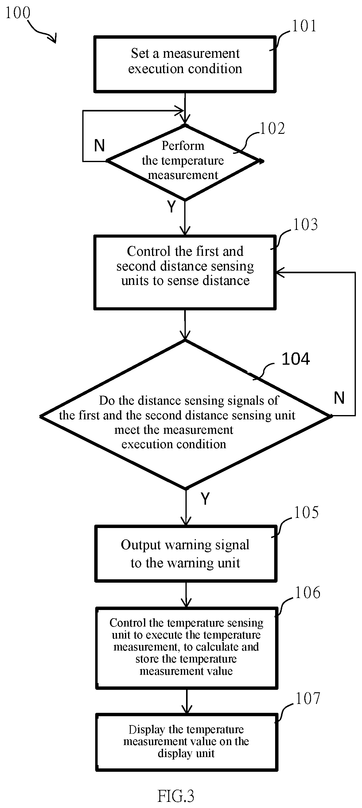
[0047]Please refer to FIG. 3, which shows a flow chart of a measurement alignment method of the present invention. In this embodiment, a measurement alignment method 100 can be performed by using the temperature measuring device described above, and the measurement alignment method 100 comprises following steps. In a step 101, the micro processing unit 4 sets a measurement execution condition in advance, and the measurement execution condition can be used to evaluate the first distance sensing signal and the second distance sensing signal outputted from the first and second distance sensing units 1 and 2, as shown in FIG. 2; and, the measurement execution condition can be set in consideration of the first predetermined signal and the second predetermined signal which indicate the distance sensing signals outputted from the first and second distance sensing units 1 and 2 in the predetermined distances d1 and d2 shown in FIG. 2, respectively; or, the measurement execution condition ca...

second embodiment

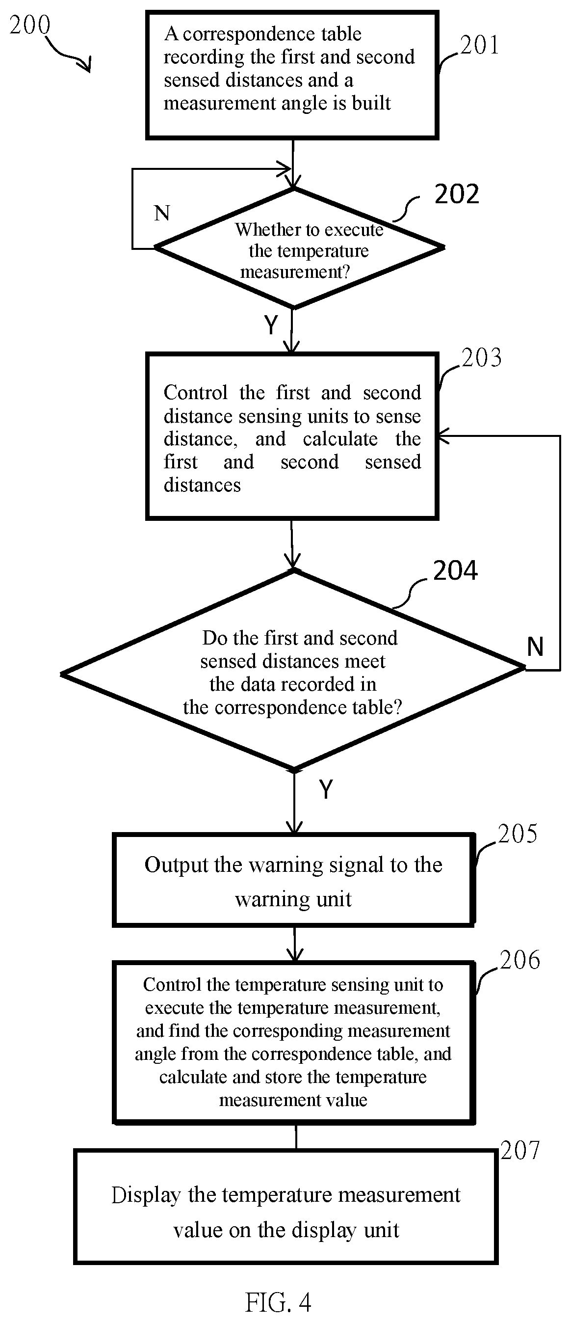
[0051]Please refer to FIG. 4, which shows a flow chart of a measurement alignment method of the present invention. In this embodiment, the measurement alignment method 200 is applied to the temperature measuring device, and comprises following steps. In a step 201, the correspondence table, which records the first and second sensed distances and a measurement angle, is built in the micro processing unit 4 in advance. The correspondence table can be built by doing experiments in which the user operates the temperature measuring device at a correct position to measure temperature, to find a corresponding relationship between the tolerable measurement angle and the first and second sensed distances d1 and d2, as shown in FIG. 2, under the acceptable temperature measurement result. In a step 202, the micro processing unit 4 determines whether to execute the temperature measurement, for example, the micro processing unit 4 can determine according to the trigger signal of the button unit ...

third embodiment

[0053]Please refer to FIG. 5, which shows a flow chart of a measurement alignment method of the present invention. In this embodiment, the measurement alignment method 300 is applied to the temperature measuring device, and comprises following steps. In a step 301, the correspondence table, which records the first and second sensed distances and the measurement angle, is built in the micro processing unit 4. The correspondence table can be obtained by doing the experiment in which the user operates the temperature measuring device at the correct position to measure temperature, to find the corresponding relationship between the tolerable measurement angle and the first and second sensed distances d1 and d2 shown in FIG. 2, under the acceptable temperature measurement result. In a step 302, the micro processing unit 4 determines whether to execute the temperature measurement, and the micro processing unit 4 can determine according to the trigger signal of the button unit 5, if the bu...


PUM

PropertyMeasurementUnit
distanceaaaaaaaaaa
temperatureaaaaaaaaaa
distanceaaaaaaaaaa

Abstract

A temperature measuring device includes at least one first distance sensing unit and a second distance sensing unit for outputting first and second distance sensing signals, respectively; a temperature sensing unit for outputting a temperature sensing signal; a display unit for displaying the temperature measurement value; and a micro processing unit for receiving the first and the second distance sensing signals, and then determining, according to the first and the second distance sensing signals, whether the display unit displays the temperature measurement value calculated according to the temperature sensing signal. As a result, the at least two distance sensing units are used to prevent the temperature measuring device from executing the temperature measurement when the sensing unit of the thermometer obliquely points to a to-be-sensed part of a to-be-measured target to cause a large measurement angle.

Description

NOTICE OF COPYRIGHT[0001]A portion of the disclosure of this patent document contains material which is subject to copyright protection. The copyright owner has no objection to any reproduction by anyone of the patent disclosure, as it appears in the United States Patent and Trademark Office patent files or records, but otherwise reserves all copyright rights whatsoever.BACKGROUND OF THE PRESENT INVENTIONField of Invention[0002]The present invention relates to a temperature measuring device and a method thereof. More particularly, the present invention relates to a temperature measuring device with measurement alignment function, and a method thereof.Description of Related Arts[0003]In recent years, the traditional contact thermometers, such as mercury or electronic thermometers, can no longer meet the needs of users, so there is a need to develop a temperature measuring method and device to provide accurate, fast, simple, easy-to-interpret, no-harm, and human-friendly temperature m...

Claims


Application Information

Patent Timeline
Patent Type & Authority Patents(United States)
IPC IPC(8): G01J5/02A61B5/00G01J5/00G01K13/20
CPCG01J5/0275A61B5/7221G01J5/0022G01J5/0025G01J5/025G01J5/0265G01K13/223G01J2005/0048G01J5/80
Inventor YANG, TA CHIEHSHIH, HSUAN HAOOU YANG, HSING
Owner AVITA
Learn More