Supercharge Your Innovation With Domain-Expert AI Agents!

Wireless mouse and switch module applied therein

a switch module and wireless mouse technology, applied in the field of switches and mouse, can solve the problems of high manufacturing cost of bluetooth mouse, loss problem of conventional wireless mouse, etc., and achieve the effect of reducing the assembling space of the switch module, and reducing the manufacturing cos

Active Publication Date: 2021-09-14
CHENG UEI PRECISION IND CO LTD
View PDF12 Cites 1 Cited by
  • Summary
  • Abstract
  • Description
  • Claims
  • Application Information

AI Technical Summary

Benefits of technology

[0011]As described above, when the operation portion of the pressing button is pushed frontward and rearward, the at least one extending foot drives the first switch of the circuit board to realize a power function, when the operation portion of the pressing button is located at the first position, the at least one extending foot is without driving the first switch, at the moment, the power function is turned off, when the operation portion of the pressing button is located at the second position, the at least one extending foot drives the first switch, at the moment, the power function is turned on, the operation portion is capable of being pressed towards the circuit board to make the extending arm press the second switch of the second the circuit board to execute a bluetooth pairing function. As a result, the switch module is capable of reducing a manufacturing cost to have a lower cost and reducing an assembling space of the switch module to save an occupying space.

Problems solved by technology

However, the conventional wireless mouse need provide the USB adaptor to the user, and the conventional wireless mouse is rather smaller in size, so when the conventional wireless mouse is used, the conventional wireless mouse will have a loss problem.
Furthermore, the bluetooth mouses on the market, the power switch and a bluetooth pairing key of the bluetooth mouse are mostly two independent and separated structures, so the bluetooth mouse has a higher manufacturing cost and a larger space is considered to mount the power switch and the bluetooth paring key in the bluetooth mouse.

Method used


Image

  • Wireless mouse and switch module applied therein
  • Wireless mouse and switch module applied therein
  • Wireless mouse and switch module applied therein

Examples


Embodiment Construction

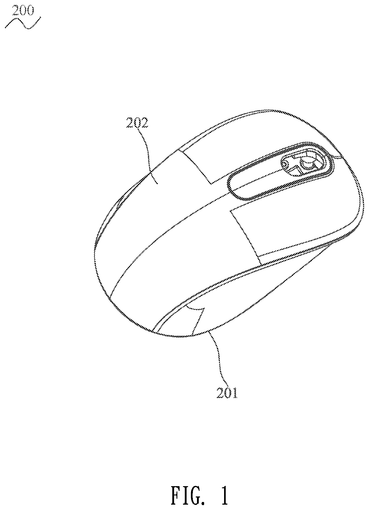
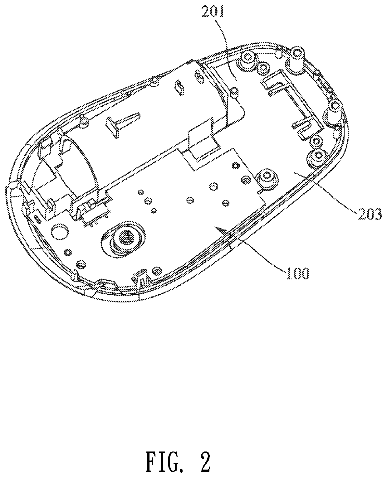
[0022]With reference to FIG. 1 to FIG. 3, a switch module 100 and a wireless mouse 200 in accordance with a preferred embodiment of the present invention are shown. The switch module 100 is applied in the wireless mouse 200. The wireless mouse 200 includes a lower shell 201, the switch module 100 and an upper shell 202. The switch module 100 is mounted to the lower shell 201 of the wireless mouse 200. The switch module 100 is mounted between the lower shell 201 and the upper shell 202. The upper shell 202 is covered to the lower shell 201 to form an accommodating space 203 between the upper shell 202 and the lower shell 201. The switch module 100 is accommodated in the accommodating space 203. In a specific implementation, the switch module 100 is also capable of being assembled to other types of equipments.

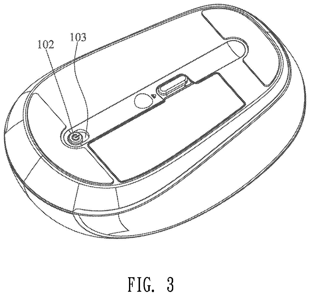
[0023]With reference to FIG. 1 to FIG. 9, the switch module 100 includes a pressing button 1, a supporting block 2, a circuit board 3, and a screw 4. The pressing button 1 is dis...


PUM


Abstract

A switch module includes a pressing button, a supporting block and a circuit board. The pressing button has a first surface and a second surface. The second surface of the pressing button has an operation portion. The operation portion is equipped with an extending arm. At least one portion of one side of the first surface of the pressing button protrudes upward to form at least one extending foot. The supporting block supports the pressing button. The supporting block has a third surface and a fourth surface. The circuit board faces to the third surface of the supporting block. The circuit board has a fifth surface and a sixth surface. The circuit board is equipped with a first switch. The sixth surface of the circuit board is equipped with a second switch. The first switch is disposed corresponding to the at least one extending foot.

Description

CROSS-REFERENCE TO RELATED APPLICATION[0001]The present application is based on, and claims priority from, China Patent Application No. 201921625658.6, filed Sep. 27, 2019, the disclosure of which is hereby incorporated by reference herein in its entirety.BACKGROUND OF THE INVENTION1. Field of the Invention[0002]The present invention generally relates to a switch and a mouse, and more particularly to a wireless mouse, and a switch module applied in the wireless mouse which has a lower cost and saves an occupying space.2. The Related Art[0003]As is known to all, a wireless mouse has a wireless transmission capacity and is capable of being paired with a computer host to be used by a wireless technology. When a user operates the wireless mouse, the wireless mouse is used without a limitation of a cable, so the wireless mouse is used quite conveniently.[0004]Generally, when a conventional wireless mouse is paired with the computer host, a USB (Universal Serial Bus) adaptor need be inser...

Claims


Application Information

Patent Timeline
Patent Type & Authority Patents(United States)
IPC IPC(8): G06F3/033G06F3/0354G06F3/02H01H13/52
CPCG06F3/03543G06F3/02H01H13/52G06F3/0383G06F2203/0384H01H15/005H01H2025/004H01H2239/014
Inventor LEE, TSUNG SHIH
Owner CHENG UEI PRECISION IND CO LTD
Features
  • R&D
  • Intellectual Property
  • Life Sciences
  • Materials
  • Tech Scout
  • Unparalleled Data Quality
  • Higher Quality Content
  • 60% Fewer Hallucinations
Learn More