Inductor component

a technology of inductor components and components, applied in the direction of transformers/reacts mounting/support/suspension, inductances, inductances, etc., can solve the problems of interference between the inductor component and the adjacent device, for example, and achieve the effect of increasing the design flexibility of the terminal electrode of the inductor component and the land pattern on the circuit board

Active Publication Date: 2021-09-21
MURATA MFG CO LTD
View PDF33 Cites 0 Cited by
  • Summary
  • Abstract
  • Description
  • Claims
  • Application Information

AI Technical Summary

Benefits of technology

[0007]The inductor component having this structure can be easily placed in a stable position in the mounting process. In addition, the gap between the inductor component mounted on the circuit board and a component mounted adjacent to the inductor component can be increased at the top side. Thus, the risk of interference between the components due to, for example, tilting of the components can be reduced.
[0026]In the above-described inductor component, preferably, the side electrode section includes two portions having different inclinations, and an inclination one of the two portions that is adjacent to an inner face of the support is greater than an inclination of other of the two portions that is adjacent to the end face. With this structure, the design flexibility of the terminal electrode of the inductor component and the land pattern on the circuit board can be increased.

Problems solved by technology

Thus, there is a risk that the inductor component and a device adjacent to the inductor component, for example, will interfere with each other.

Method used


Image

  • Inductor component
  • Inductor component
  • Inductor component

Examples


first embodiment

[0049]A first embodiment will now be described.

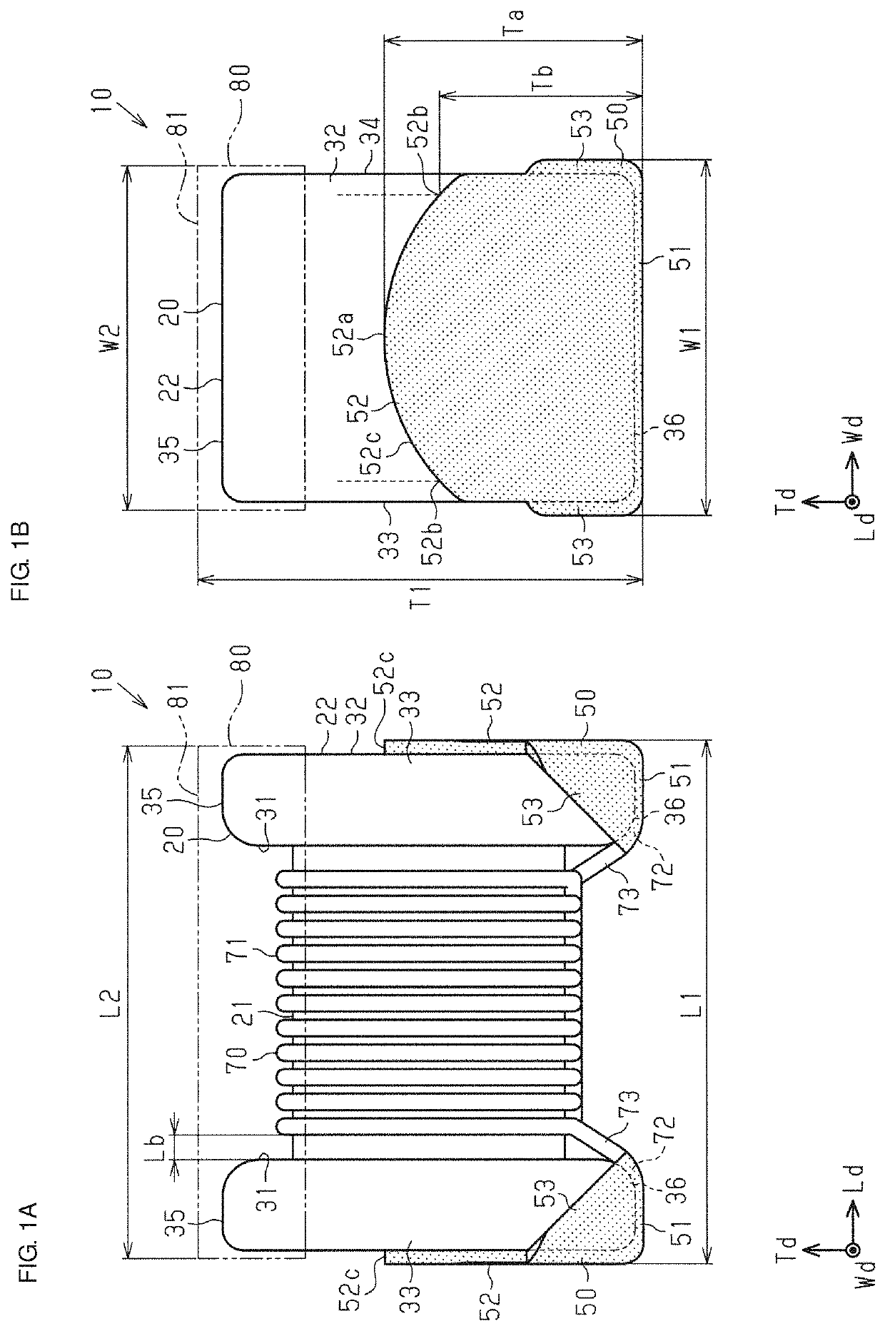
[0050]An inductor component 10 illustrated in FIGS. 1A, 1B, and FIG. 2 is, for example, a surface-mount inductor component to be mounted on, for example, a circuit board. The inductor component 10 may be used in various devices, such as smart phones and wrist-worn mobile electronic devices (for example, smart watches).

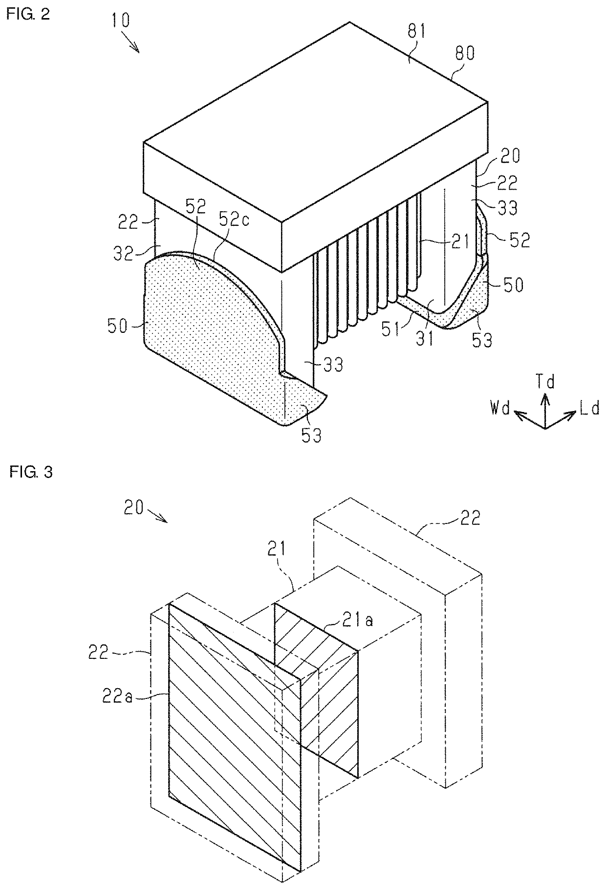
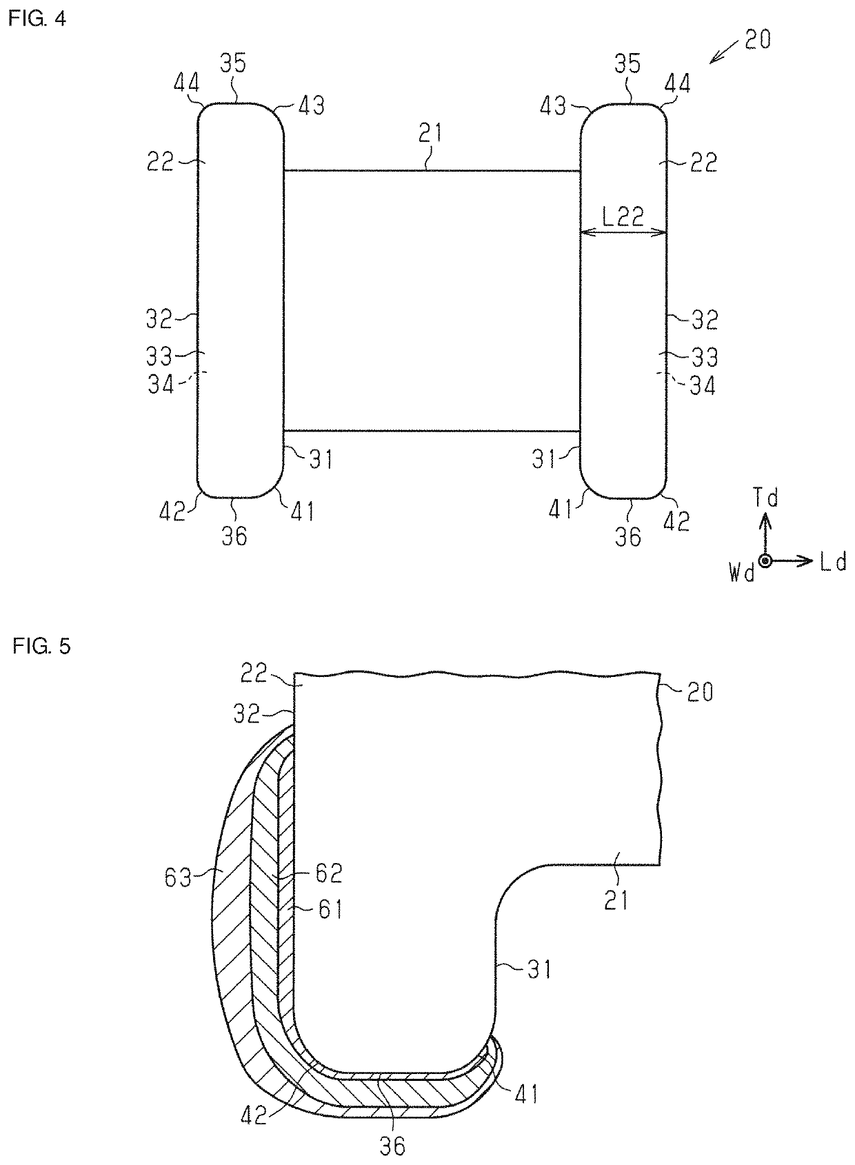
[0051]The inductor component 10 according to the present embodiment includes a core 20, a pair of terminal electrodes 50, and a wire 70. The core 20 includes a shaft 21 and a pair of supports 22. The shaft 21 is substantially rectangular parallelepiped shaped (rectangular prism shaped). The supports 22 extend perpendicularly to the longitudinal direction of the shaft 21 from both ends of the shaft 21. The shaft 21 is supported parallel to a circuit board by the supports 22. The supports 22 are formed integrally with the shaft 21 at both ends of the shaft 21.

[0052]The terminal electrodes 50 are formed on the respective supp...

second embodiment

[0124]A second embodiment will now be described.

[0125]In this embodiment, constituent members that are the same as those in the above-described embodiment are denoted by the same reference numerals, and description thereof may be partially or entirely omitted.

[0126]An inductor component 10a illustrated in FIGS. 8A, 8B, and 9 includes the core 20, the pair of terminal electrodes 50, and a wire 70a. The wire 70a is wound around the shaft 21 so as to form a single layer on the shaft 21. Both end portions of the wire 70a are connected to the respective terminal electrodes 50. The inductor component 10a is a wire-wound inductor component.

[0127]As illustrated in FIG. 8A, the wire 70a includes a wound portion 71 wound around the shaft 21, connected portions 72 connected to the terminal electrodes 50, and extending portions 73 that extend between the wound portion 71 and the connected portions 72. The connected portions 72 are connected to the bottom electrode sections 51 of the terminal el...


PUM

PropertyMeasurementUnit
lengthaaaaaaaaaa
heightaaaaaaaaaa
thicknessaaaaaaaaaa

Abstract

An inductor component includes a core including a substantially column-shaped shaft and a support formed on an end portion of the shaft, a terminal electrode formed on the support, and a cover member that covers at least an upper face of the shaft. A width dimension of the inductor component including the core and the terminal electrode is greater than a width dimension of the cover member.

Description

CROSS-REFERENCE TO RELATED APPLICATION[0001]This application claims benefit of priority to Japanese Patent Application No. 2017-086206, filed Apr. 25, 2017, the entire content of which is incorporated herein by reference.BACKGROUNDTechnical Field[0002]The present disclosure relates to an inductor component including a core and a wire wound around the core.Background Art[0003]Various types of inductor components are mounted in electronic devices. A wire-wound inductor component includes a core and a wire wound around the core. The end portions of the wire are connected to terminal electrodes formed on the core (see, for example, Japanese Unexamined Patent Application Publications Nos. 2002-280226 and 10-321438). Each terminal electrode is connected to a pad by, for example, solder, the pad being formed on a circuit board or the like on which the inductor component is mounted.SUMMARY[0004]Electronic devices, such as cellular phones, have become smaller, and there has been a demand for...

Claims


Application Information

Patent Timeline
Patent Type & Authority Patents(United States)
IPC IPC(8): H01F17/04H01F27/29H01F27/02H01F27/28H01F27/26H01F27/38
CPCH01F27/292H01F17/045H01F27/022H01F27/26H01F27/2828H01F27/38H01F27/06H01F27/29H01F27/306H01F2027/065H01F2027/297
Inventor TANAKA, AKIRA
Owner MURATA MFG CO LTD
Why Eureka
Try Eureka